
Thermal and Thermo-Structural Analysis
Heat transfer and thermal stress analysis in ANSYS for equipment that runs hot, heats up unevenly or cools down slowly, checked to the governing code.
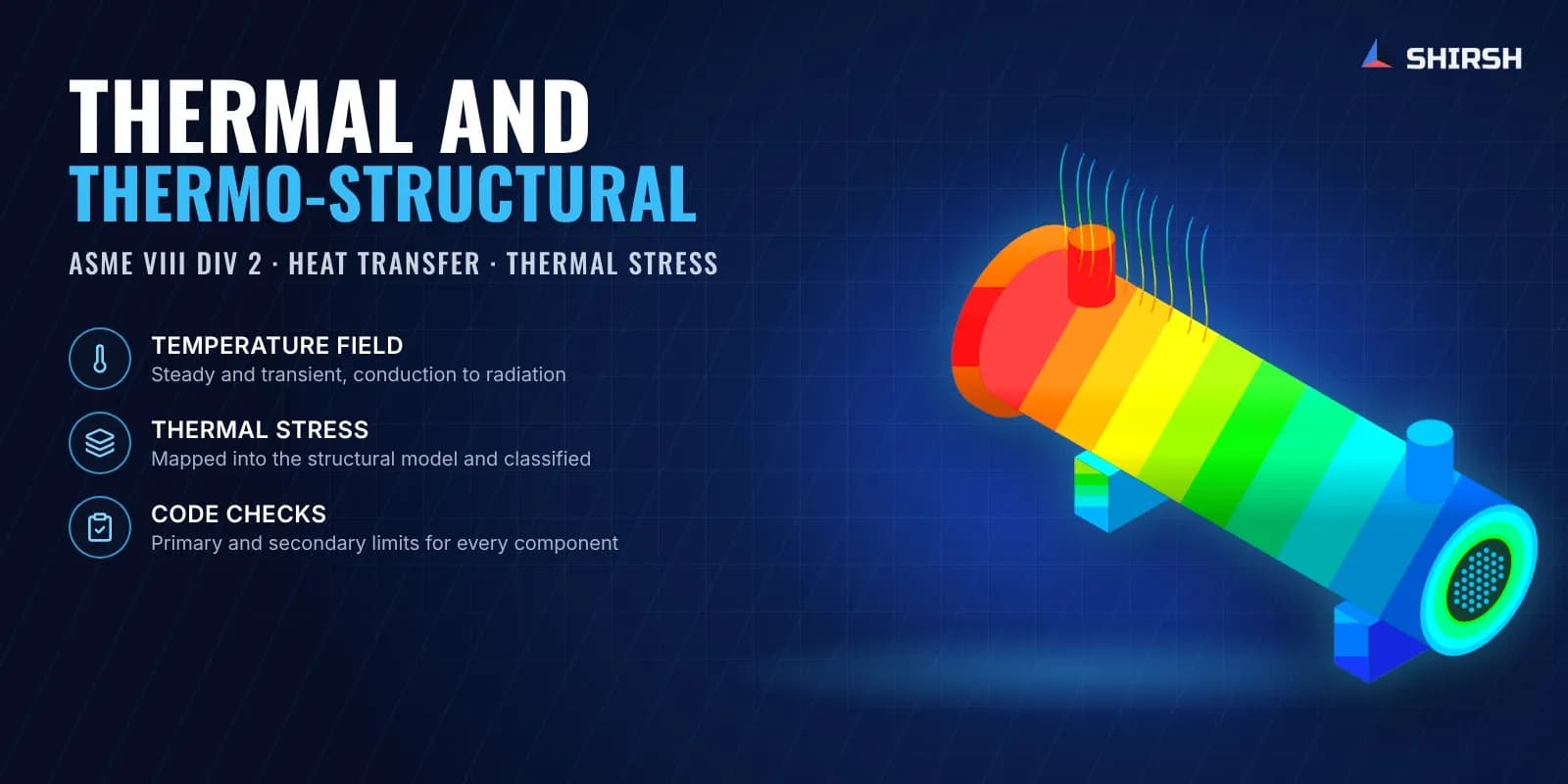
What this solution covers
Temperature quietly changes everything in a design. Steel loses strength as it heats, and parts in contact grow at different rates. Even when the pressure is low, a gradient through a thick wall sets up its own stress. So a flange that leaks only after heat-up, or a weld that cracks after a few start-ups, is usually a thermal problem that a pressure check alone will not show.
Shirsh Technosolutions solves the temperature field first and then carries it into the structural model. Conduction, convection and radiation are handled in ANSYS Mechanical, steady or transient, and ANSYS Fluent is used when the airflow or fluid flow decides the temperatures. Material properties change with temperature in our models, and the thermal stresses are classified and checked against the code the equipment is built to.
Pain points we address
Parts pass the pressure check but leak, distort or crack once they run hot
Nobody can say how long the equipment takes to heat up or cool down
Reviewers want thermal stress separated from pressure stress and classified
Electronics or panels overheat inside enclosures in summer
Heat lost through supports and insulation breaks has never been quantified
What we solve
Steady-state and transient heat transfer by conduction, convection and radiation
Conjugate heat transfer where air or fluid flow sets the temperatures
Thermal stress and distortion with temperature-dependent material properties
Heat-up, cool-down and thermal shock cases for vessels, exchangers and valves
Weld thermal history for multi-pass welds
Thermal design of enclosures, heatsinks and liquid cooling plates
How we approach it
- 1
Agree the operating, start-up and upset temperatures and the governing code
- 2
Collect material data with properties that vary with temperature
- 3
Solve the temperature field, transient wherever timing matters
- 4
Map the temperatures into the structural model with pressure, preload and self-weight
- 5
Linearise and classify stresses, then check primary and secondary limits
- 6
Report the hotspots and the changes that bring them within limits
Deliverables
Thermal and thermo-structural analysis report
Temperature and stress contour plots, with time histories for transient cases
Code check tables for each component
Recommendations for design or operating changes
ANSYS model files for clients holding an ANSYS licence
Expected outcomes
Temperature and stress results that stand up in client and third-party review
Thermal problems found on the screen, before the first heat-up on site
Heating and cooling times that operations can plan around
Design changes justified by calculation instead of extra margin
Why Shirsh
Our thermal work spans process equipment and electrical equipment. We have run transient cooling studies of catalyst silos and hoppers, thermal-structural checks of waste heat boiler coils and preheaters, heat loss through fire-proofed vessel saddles and thermal shock on exchanger tubesheets. On valves we have analysed body, bonnet, seats and bolting at operating temperature and simulated the thermal history of multi-pass welds. On the electrical side we have sized enclosure air conditioning, studied inverter enclosures and designed heatsinks and liquid cooling plates.
Where the equipment falls under ASME Section VIII Division 2, thermal stresses are linearised and treated as secondary stress in the Pm, PL+Pb and PL+Pb+Q checks, the way reviewers expect to see them.
Where this lives
Related case studies
CFD of Mixing and Heat Transfer in a Jacketed Agitated Reactor
MRF CFD of a jacketed reactor with dual hydrofoil impellers and a bottom tickler, checking circulation, dead zones and wall heat transfer before fabrication.
ReadTransient Thermal Analysis of an FCC Catalyst Cooling Silo and Hopper
Transient thermal FEA of a refinery FCC catalyst cooling silo and hopper, with conduction, convection and radiation, to size natural and air-pad cooling.
ReadTransient Thermal Simulation of Multi-Pass Valve Welding
Transient thermal FEA of a multi-pass field weld on a trunnion-mounted ball valve, checking that the soft seals stay below their temperature limit on an accelerated welding schedule.
ReadBESS Container CFD and Structural FEA: Cooling Airflow, Wind and Seismic Checks
CFD of cooling airflow around battery racks and FEA of the container for wind and seismic loads, so a BESS integrator could fix its layout early.
ReadTransient CFD of a Controlled Cooling Conveyor for Hot Steel Castings
Transient CFD of a casting cooling conveyor: blower jets and casting temperature tracked zone by zone to size the blowers before the line was built.
ReadRelated insights
BESS Container HVAC: Why One Rack Runs Hot and What CFD Shows
A BESS container HVAC unit controls on its return air, and that reading can stay the same while the racks inside breathe very different air. We ran four OpenFOAM cases on a generic ten-rack container to show which rack ran hottest, why 30% more airflow barely changed the pattern, and how swapping the supply and return closed most of the gap.
ReadLiquid Cooling Flow Split Across Cold Plates: What CFD Shows
A CDU sees one flow and one pressure, so it cannot tell you whether every cold plate on a rack manifold gets its share. We ran five OpenFOAM cases on an eight-branch manifold to show how the return arrangement and plate pressure drop set the split, and why one fouled plate can hide behind a healthy CDU reading.
ReadPG25 Drift in Direct-to-Chip Loops: Where the Cold Plates Feel It
ASHRAE TC 9.9's May 2026 bulletin lists coolant composition first among the ways a direct-to-chip loop drifts. We ran six OpenFOAM conjugate heat transfer cases on a generic copper cold plate: at the same flow, PG35 needs 34.3% more pressure than PG25, while the loop temperature rise at the CDU moves only from 10.00 K to 10.26 K.
ReadHot-Aisle Containment: What CFD Shows That Rack Inlet Sensors Miss
A rack inlet sensor at mid-height can read 20 °C on every rack while 28.7 percent of the inlet area is above the 27 °C recommended limit. A small OpenFOAM study of one rack row, with and without hot-aisle containment, shows where the hot air gets in and why containment only helps once the airflow matches the racks.
ReadWant to learn this?
We also offer ANSYS & SolidWorks training courses.
At a glance
Discuss your project with our engineers
Tell us about your simulation, validation or design challenge.