PG25 Drift in Direct-to-Chip Loops: Where the Cold Plates Feel It
ASHRAE TC 9.9's May 2026 bulletin lists coolant composition first among the ways a direct-to-chip loop drifts. We ran six OpenFOAM conjugate heat transfer cases on a generic copper cold plate: at the same flow, PG35 needs 34.3% more pressure than PG25, while the loop temperature rise at the CDU moves only from 10.00 K to 10.26 K.
Read the full article below for the methodology, the data, and the engineering decisions behind it.
Most direct-to-chip cooling loops behind a coolant distribution unit (CDU) run on a propylene glycol and water mix, and the usual specification is about 25% glycol, written PG25. In May 2026 ASHRAE Technical Committee 9.9 issued a technical bulletin, "TCS Coolant Integrity and System Readiness Best Practices", on how these technology cooling system (TCS) loops drift away from their design condition between commissioning and steady operation.
The first item on its list is coolant composition. This note asks a narrow question about it: if a loop designed for PG25 ends up at PG20, PG30 or PG35, which part of the loop notices? We answered it first by hand and then with a conjugate heat transfer CFD model of a generic copper cold plate in OpenFOAM.
1. What the bulletin says
The bulletin is a companion to the committee's 2024 document "Liquid Cooling: Resiliency Guidance for Cold Plate Deployments". It names a nominal PG25 mix, asks that the glycol meet TC 9.9's minimum quality guidance or the IT manufacturer's specification, and calls for a structured technical review before coolants are mixed. It then sets out four ways a loop drifts.
Coolant composition. A change in concentration changes viscosity, density, specific heat and conductivity, which moves the pressure drop, the pump operating point, heat exchanger effectiveness and the stability of CDU control. Concentration should be checked in a laboratory at fill, after any make-up addition and at intervals after that.
Air in the loop. Entrained air cuts heat transfer, cavitates pumps and speeds up corrosion. Degassing works best at higher temperatures, so trouble can show up weeks after start-up.
Stainless steel passivation. Welding, grinding and field fabrication damage the chromium oxide film, and re-passivation is to ASTM A380 or ASTM A967.
Pressure ratings. A full hydraulic model should cover flush and fill pressures, static height, relief settings, expansion tank pre-charge and transients. The report cites the IEC 62368-1 hydrostatic test at 1.5 times the rated maximum working pressure.
The facility water classes in the fifth edition of ASHRAE's Thermal Guidelines (W17, W27, W32, W40, W45 and W+) describe the water that reaches the CDU. The bulletin is about the closed loop on the other side of the CDU, the one that runs through the cold plates.
2. The hand check
Take a loop carrying 1 kW per plate with a 10 K rise, 30 °C supply and 40 °C return, and fluid properties at the 35 °C mean from the Melinder (2010) correlations. For PG25 that needs 1.498 L/min per kW. Hold the pump at that flow and change the fluid. Going from PG25 to PG35, the loop temperature rise moves from 10.00 K to only 10.26 K, because density and specific heat change in opposite directions and nearly cancel, so the CDU's supply and return sensors would hardly notice.
The viscosity rises from 1.542 to 2.128 mPa·s. If the plate passages ran fully developed laminar flow, their pressure drop would rise in proportion, by 38%. That is the number a quick estimate gives. The CFD below tests how much of it a real plate geometry keeps.
3. The CFD model
The plate is generic: a 50 by 30 mm copper plate with a 1 mm base and a 30 mm long field of 0.5 mm channels between 0.5 mm fins, 3 mm tall, fed from full-width inlet and outlet slots through 10 mm plenums. A 20 by 20 mm chip footprint under the base puts in 1 kW. The pump flow is fixed at 1.498 L/min in every case.

Figure 1. The model. Half the plate was solved with a symmetry plane on the centre line.
We solved the coolant and the copper together with OpenFOAM's chtMultiRegionSimpleFoam: steady, laminar, constant fluid properties at 35 °C, copper conductivity 390 W/m·K. The half model has 144,000 cells, with three cells across each channel. Each case ran until the plate pressure drop and the chip footprint temperature changed by less than 0.5% over the last 250 iterations.
4. What the plate sees
Six cases, all at the same flow. A is the design fluid. B, C and D are concentration drift, E is plain water and F is a cold fill.
Case | Fluid | Plate pressure drop (Pa) | Change vs A | Chip footprint, average rise above inlet (K) | Peak base temperature (°C) |
|---|---|---|---|---|---|
A | PG25, design | 1260.0 | - | 69.40 | 118.20 |
B | PG30 | 1455.7 | +15.5% | 71.54 | 120.74 |
C | PG35 | 1691.7 | +34.3% | 73.81 | 123.42 |
D | PG20 | 1097.9 | -12.9% | 67.39 | 115.79 |
E | Water | 662.0 | -47.5% | 60.39 | 107.39 |
F | PG25 at 20 °C, no heat | 1923.5 | +52.7% | - | - |

Figure 2. OpenFOAM results for the six cases, computed for this note.
At PG35 the plate needs 34.3% more pressure for the same flow, against the 38% of the hand estimate. Across the fin field alone the rise is 32.4%. The difference is the entry length: with channel Reynolds numbers of a few hundred the flow is still developing over much of the 30 mm, and that part of the loss does not scale with viscosity alone. The hand estimate is a reasonable upper bound here. It does not replace the plate's own curve.
The thermal side moves less. At PG35 the chip footprint runs 4.41 K warmer on average, and the peak on the base underside goes from 118.20 to 123.42 °C. The peak sits just downstream of the footprint centre, at about x = 27 mm, as the coolant warms along the channels. The footprint rise includes conduction through the copper base and fins, which does not depend on the fluid, so it grows less than the coolant film alone would.

Figure 3. Base underside temperature, case A against case C. Same scale for both.

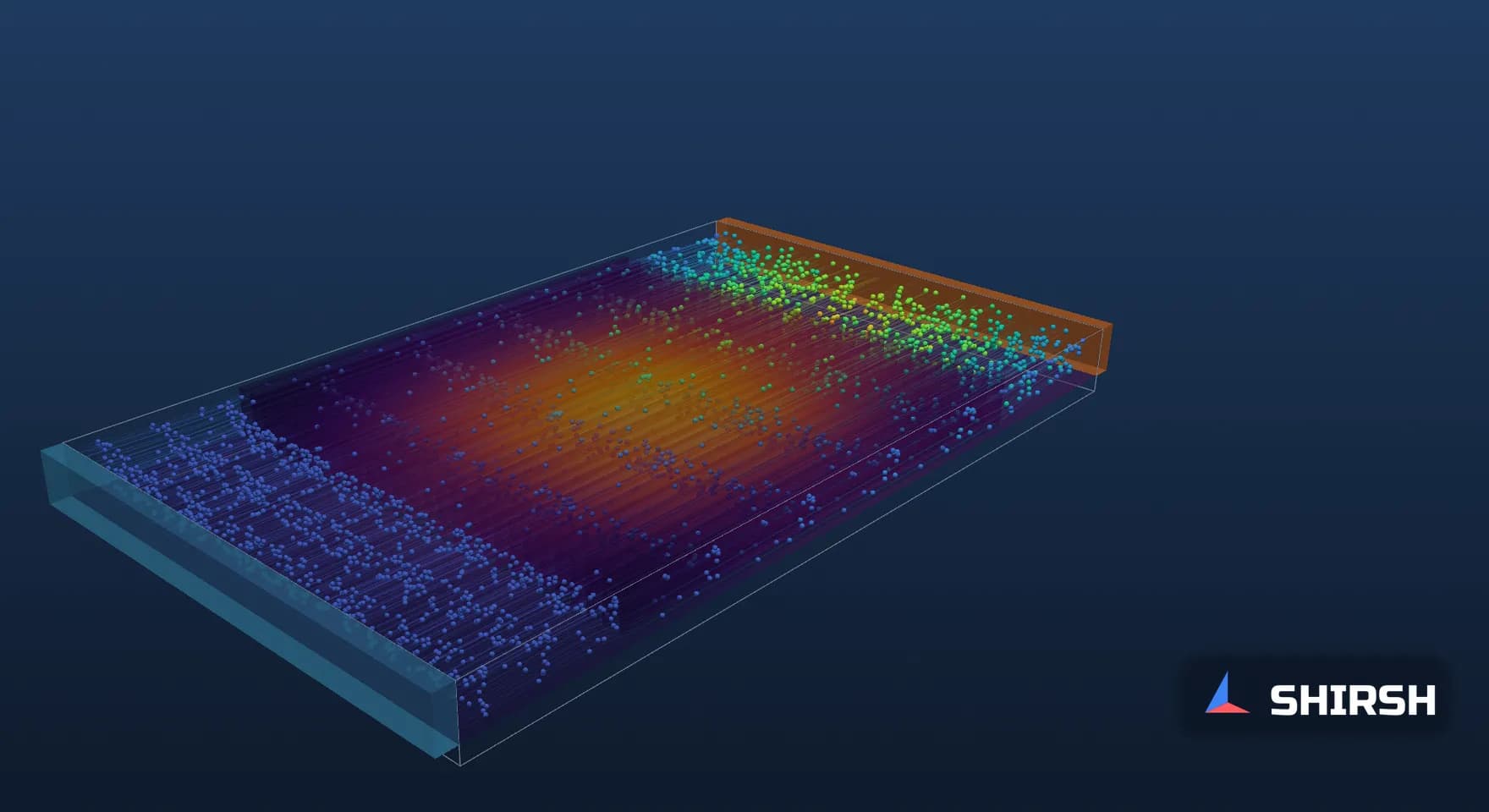
Figure 4. Case A from the 3D streamline animation, an illustration of the converged steady field. The full animation runs through all six cases.
Plain water (case E) halves the pressure drop and runs 9.02 K cooler at the footprint, but it is a different fluid with different freeze and corrosion protection, and the bulletin asks for a structured review before any change of coolant. Under-strength glycol (case D) is the same trade in a smaller dose.
5. The cold fill
PG25 at 20 °C has a viscosity of 2.45 mPa·s, 1.59 times its 35 °C value. In case F the plate needs 1923.5 Pa at the design flow, 1.527 times case A and more than the PG35 case, before the loop has carried any heat. Fill and flush pressures belong in the hydraulic model next to the operating point, which is the bulletin's fourth item.

Figure 5. Viscosity of water, PG25 and PG35 from the Melinder (2010) correlations.
6. Mesh check and limits
We repeated cases A and C on a finer mesh of 288,000 cells, with four cells across each channel instead of three and finer layers through the height. The absolute numbers move: the case A pressure drop rises from 1260.0 to 1382.2 Pa and its footprint rise falls from 69.40 to 64.89 K, so the absolute values in the table should be read as indicative for this generic plate. The comparison the note is about holds. On the fine mesh PG35 needs 34.4% more pressure than PG25, against 34.3% on the coarse mesh, and runs 3.77 K warmer at the footprint, against 4.41 K.
The model holds fluid properties constant at 35 °C, so the warmer coolant near the base is a little less viscous than modelled. The inlet and outlet are ideal slots, where a real plate has ports and a manifold of its own, and the fins are a generic design. The heat carried out by the coolant closes the energy balance to within 2% to 4% across the cases, part of the residual coming from slow fluctuation of the outlet plenum flow between iterations.
7. What this means for a loop review
A CDU reports a flow and a pair of temperatures, and a ten-point shift in glycol barely moves them. The plate sees a third more pressure drop and a few kelvin less margin at the chip. When we review a TCS design or a commissioning report, we want the concentration measured at fill and after each make-up, the cold plate pressure drop curve for the actual fluid at the actual temperature, and the cold fill case in the hydraulic model beside the 35 °C design point.
In our earlier note on flow split across cold plates, the plate pressure drop set how evenly a manifold shared its flow. A fluid change that moves every plate by the same factor leaves the split roughly as it was. A fouled or air-bound plate does not, and that is where a model of the whole manifold earns its place.
Where Shirsh fits
At Shirsh Technosolutions we model liquid cooling manifolds, cold plates and CDU loops with ANSYS Fluent and OpenFOAM, including conjugate heat transfer through the copper, pressure drop for the specified coolant and fill-temperature cases. If you are designing or commissioning a direct-to-chip loop and want the hydraulics checked against the fluid that will really be in it, please get in touch.
References
ASHRAE TC 9.9, Technical Bulletin "TCS Coolant Integrity and System Readiness Best Practices", May 2026, as reported by StorageReview, "ASHRAE TC 9.9 Flags Four Ways Direct-to-Chip Cooling Loops Go Wrong", 30 August 2026 (PG25, the four failure paths, ASTM A380/A967, IEC 62368-1 test at 1.5 times rated maximum working pressure).
ASHRAE TC 9.9, "Liquid Cooling: Resiliency Guidance for Cold Plate Deployments", 2024 (named in the same report as the companion document).
ASHRAE, Thermal Guidelines for Data Processing Environments, fifth edition, facility water classes W17 to W+, as summarised by Upsite Technologies, "Major Changes to ASHRAE's Fifth Edition of Thermal Guidelines, Part 3", 31 July 2024.
Å. Melinder, Properties of Secondary Working Fluids for Indirect Systems, International Institute of Refrigeration, 2010 (propylene glycol and water properties); water properties to IAPWS formulations.
Hand check and CFD (OpenFOAM v1912, chtMultiRegionSimpleFoam, six cases and a mesh check) computed for this note, 12 November 2026. Generic plate; not any project.
Click to view full size
Related case studies
Want to Apply This to Your Product?
Our engineers can help you implement these techniques on your specific components and assemblies.
Get insights like this in your inbox
Engineering deep-dives, simulation tips, and industry analysis. No spam, unsubscribe any time.