3D Transient Thermal Simulation of Multi Layer Valve Welding
A high fidelity thermal analysis verifying soft-seal integrity during an accelerated 8-layer welding sequence on a 16-inch Class 900 Trunnion Mounted Ball Valve

Project brief
This engineering verification project evaluates the thermal impact of a critical field welding procedure on a 16 inch ASME Class 900 Trunnion Mounted Ball Valve with a butt weld end. When welding extension pup pieces onto high pressure valve bodies, intense thermal energy propagates through the heavy steel walls. This case study details the numerical verification workflow used to predict whether internal soft-sealing components remain safe from heat degradation during aggressive manufacturing schedules.
What was at risk
The client required an evaluation of an accelerated welding procedure: depositing 8 total welding layers (GTAW root pass followed by 7 GMAW fill and cap passes) completed in a compressed timeframe of only 30 minutes total (225 seconds per layer) at an estimated weld temperature of 700°C.
The primary engineering challenge was the threat of interpass temperature accumulation within the heavy 30.96 mm thick wall (ASTM A312 TP316L Schedule 120). Two critical soft components are housed nearby:
FKM 90 AED O-ring: Located 285.5 mm from the weld end.
Devlon Valve Seat: Located 315.7 mm from the weld end.
Both materials possess a strict maximum allowable temperature limit of 160°C. Because the welding schedule was heavily compressed, the base metal lacked adequate time to cool between passes, creating a significant risk of a delayed thermal wave overwhelming and destroying the internal seals.
Solution offered
A comprehensive 3D Transient Thermal Analysis was executed within ANSYS Mechanical to map the structural heat soak over time. Instead of an excessively taxing moving torch model, an optimized "Lumped Pass" approach was utilized. This method applied a uniform volumetric or boundary thermal load to entire circumferential weld rings step-by-step, providing identical accuracy for remote components located roughly 300 mm away.
Key technical components of the solution included:
Advanced Element Birth and Death: A customized APDL command snippet was embedded into the solver tree to automatically manage multi-step simulation logic. Elements representing layers 2 through 8 were deactivated (
ekill) at time zero and sequentially reactivated (ealive) alongside their respective 700°C boundary conditions at every 225 second step interval.Nonlinear Material Modeling: Temperature dependent thermophysical properties specifically Specific Heat scaling from 490 J/kg·°C at room temperature up to 600 J/kg·°C at 700°C were mapped from the Granta material library to accurately govern the speed and dissipation of the thermal wave.
Extended Solution Domain: The simulation timeline was deliberately extended past the 30 minute welding window to capture the critical post-weld cooling phase, ensuring the delayed thermal peak was fully monitored.
Challenges we overcame
Predicting Interpass Heat Accumulation: Successfully modeled the aggressive multi-layer thermal stacking caused by compressing 8 weld layers into a brief 30-minute window.
Capturing Delayed Thermal Soaking: Mitigated false-positive safety reports by demonstrating that the highest temperatures at the O-ring and seat occurred after the welding arc was extinguished.
How we executed
- 1
Geometry Partitioning: Sliced the weld joint in SpaceClaim into 8 distinct concentric rings matching the intended pass sequence.
- 2
Material Characterization: Entered temperature-dependent thermal conductivity, density, and specific heat profiles for the CF8M cast body and TP316L pup piece.
- 3
Step Control Configuration: Structured a 9-step transient framework (8 steps of 225 seconds for active welding layers + 1 extended cooling step).
- 4
APDL Script Integration: Embedded a automated script to dynamically strip constraints from old layers and instantiate new weld passes.
- 5
Probing & Evaluation: Placed nodal temperature probes directly on the 3D surface definitions of the O-ring and seat grooves to track transient histories.
Project outcome
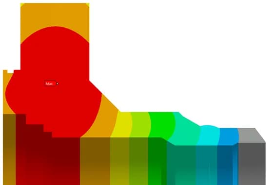
Thermal Wave Mapping: The analysis mapped out the precise time delay of the thermal energy wave traveling through the 30.96 mm pup piece wall.
Seal Integrity Verification: Peak temperatures at the Devlon seat and FKM O-ring were successfully extracted from the time-history post-processor, confirming whether they stayed within the 160°C limit.
Operational Recommendations: Provided the client with clear visibility into their safety thresholds. For configurations nearing the 160°C boundary, actionable cooling mitigation strategies—such as water-cooled heat sinks or minimum interpass cooling hold times—were mathematically validated.
Project gallery
Where this lives
Software used
Related solutions
Industries
At a glance
We apply the same rigour to every engagement
Let us show you what's possible for your product.