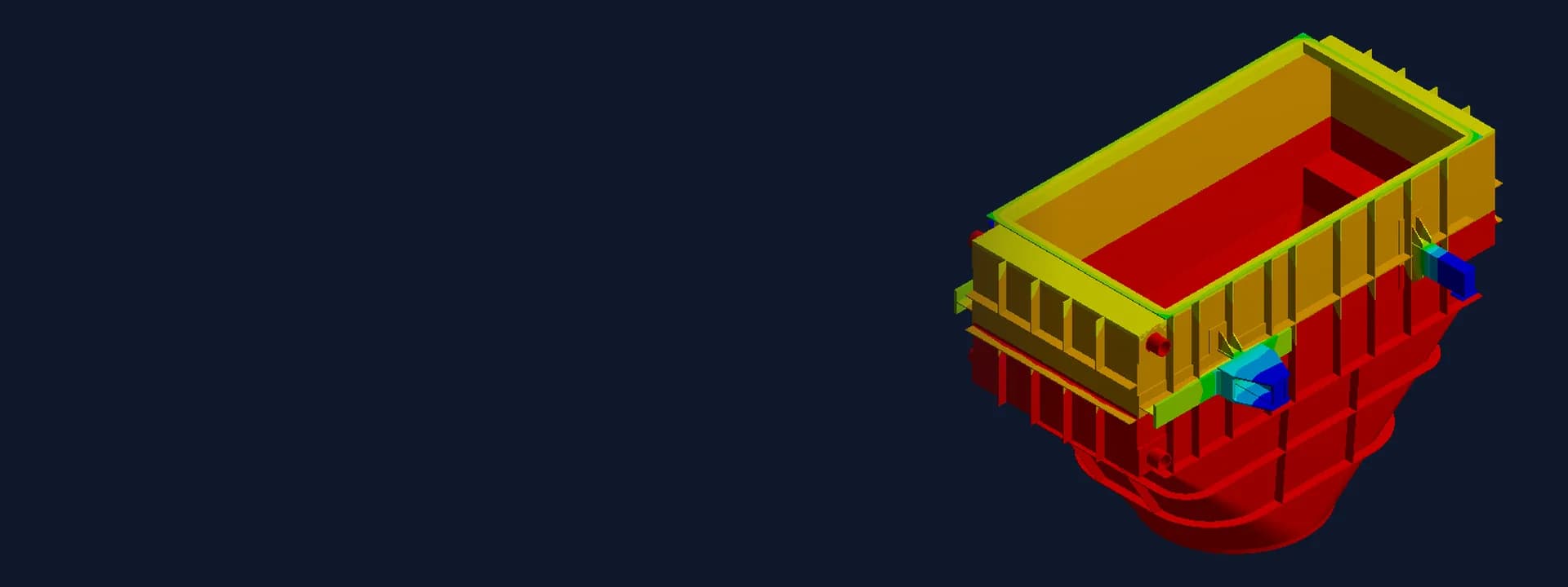
Steam Superheater FEA: ASME VIII Stress Analysis with Thermal, Wind and Seismic Loads
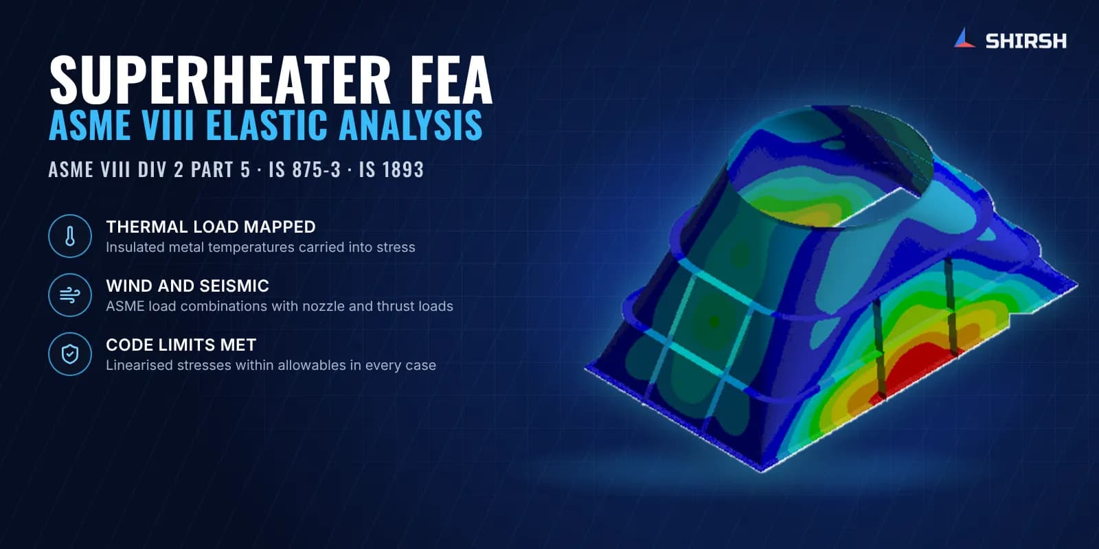
Steam superheater FEA to ASME VIII Div 2 Part 5 with thermal, wind and seismic loads, nozzle loads and linearised stress checks in ANSYS.
Project brief
A boiler and heat-exchanger fabricator was building a steam superheater for a process plant waste heat boiler. The unit is a large insulated casing in three parts: an upper hood, a mid body that carries the tube bundle, and a lower hood. Hot process gas flows through the casing while steam runs through the tubes at high pressure. The design was being checked by the process licensor, and the fabricator needed a stress analysis that would stand up to that review.
Shirsh Technosolutions carried out the steam superheater FEA in ANSYS Mechanical. The casing was assessed with the elastic analysis route of ASME Section VIII Division 2 Part 5, using allowable stresses from ASME Section II Part D for Division 1 construction. The study covered internal pressure, dead weight, the temperature field through the insulation, wind to IS 875 Part 3, seismic load to IS 1893 Part 1, and the nozzle, duct and thrust loads given by the client.
What was at risk
This is not a simple pressure vessel. The casing is built from thin stainless plate with a carbon steel upper hood, stiffened by a grid of ribs and flanges, and it runs hot. Metal temperatures vary from one end to the other, so the mid body sees a temperature gradient along its length while the hoods sit at their own levels. Thermal expansion against the supports and stiffeners can give stresses as large as those from pressure.
Several other loads act at the same time. The tube bundle hangs on the baffles, the steam headers push on the casing with pressure thrust, and the gas ducts and nozzles bring their own operating and occasional loads. Wind and earthquake act on a heavy unit sitting on four lugs, each with a different restraint.
The licensor's reviewer had commented on earlier issues of the analysis, and preliminary results had shown high stress at the upper hood and around the lugs of the mid body. The fabricator needed a complete, code-based answer covering every load combination, with each comment closed.
Solution offered
Shell and solid model of the full unit. We built a combined shell and solid model of the upper hood, mid body and lower hood from the fabricator's drawings, with second-order elements and local refinement at the junctions and lug regions. Corrosion allowance and mill tolerance were deducted from the plate and header thicknesses. The tube bundle and fluid were applied as distributed mass on the baffle holes, and an equivalent density took care of the insulation weight. Mesh quality was checked against the ASME Division 2 requirements.
Thermal analysis through the insulation. A separate steady-state thermal model included the steel shell, mineral wool insulation and aluminium cladding, with temperature-dependent conductivity. Inner wall temperatures came from the design data, and convection was applied at the outer cladding. The resulting temperature field was mapped as the thermal load for the operating case, so the expansion stresses reflect the real temperature distribution rather than a single design temperature.
Code load combinations. Load cases followed ASME VIII Division 2 Part 5, Table 5.3: pressure, dead weight and thermal load together, and pressure with dead weight plus earthquake or wind in each horizontal direction. Wind pressure was worked out to IS 875 Part 3 (2015) with an allowance for the insulation. The seismic coefficient came from IS 1893 Part 1, using the natural period from a modal analysis of the full unit. Nozzle operating and occasional loads, duct loads and header thrust were applied in each relevant case. The upper hood was analysed on its own and its support reactions were passed to the mid body and lower hood model.
Stress linearisation and assessment. Peak locations were checked by stress linearisation through the wall. Local membrane stress was compared with 1.5S, and membrane plus bending with 1.5S for the sustained cases or with 3S including secondary stress for the thermal case. Support reactions and a global equilibrium check confirmed the model was in balance.
Closing the review comments. The final issue went out with a comment resolution sheet answering the licensor's and fabricator's comments on the earlier revisions.
Common questions
Why include the temperature field in a superheater stress analysis? A superheater casing runs hot and its temperature changes along its length and through the insulation. The expansion this causes, restrained by stiffeners and supports, adds secondary stress that can be as large as the pressure stress. Mapping the real temperature field into the structural model gives a fair picture of those stresses, which ASME VIII Division 2 then limits separately as primary plus secondary.
Can ASME VIII Division 2 Part 5 be used for a Division 1 vessel? Yes. Division 1 has no detailed rules for complex shapes and load combinations, so the elastic stress analysis method of Division 2 Part 5 is often used for those parts, with stress categories and combinations from Division 2 and allowable stresses from Section II Part D for Division 1 materials.
Challenges we overcame
Thin stiffened plate casing running hot, with a temperature gradient along the mid body
Mixed materials, with a carbon steel upper hood on stainless steel mid body and hoods
Tube bundle weight, header thrust, nozzle and duct loads acting together with pressure
Wind and seismic loads on a heavy unit carried on four differently restrained lugs
A licensor review with comments to close before the design could be accepted
How we executed
- 1
Built a shell and solid model of the upper hood, mid body and lower hood from the fabrication drawings
- 2
Deducted corrosion allowance and mill tolerance, and applied tube bundle and insulation weight as mass
- 3
Ran a steady-state thermal model through the steel, mineral wool and aluminium cladding
- 4
Mapped the temperature field into the structural model for the operating case
- 5
Worked out wind pressure to IS 875 Part 3 and the seismic coefficient to IS 1893 from a modal run
- 6
Applied pressure, nozzle, duct and thrust loads in the ASME VIII Division 2 Part 5 load combinations
- 7
Linearised stresses at the critical sections and compared them with the code limits
- 8
Checked support reactions and global equilibrium, and issued the report with a comment resolution sheet
Project outcome
The superheater casing met the ASME VIII Division 2 elastic analysis limits, with Division 1 allowable stresses, in every load combination.
Deformation was in the expected direction and of acceptable size for the operating, wind and seismic cases.
The final report and comment resolution sheet answered the licensor's review comments on the earlier issues.
Support reactions for every load case were handed over for the design of the supporting structure.
Project gallery
Where this lives
Software used
Related solutions
Industries
At a glance
We apply the same rigour to every engagement
Let us show you what's possible for your product.