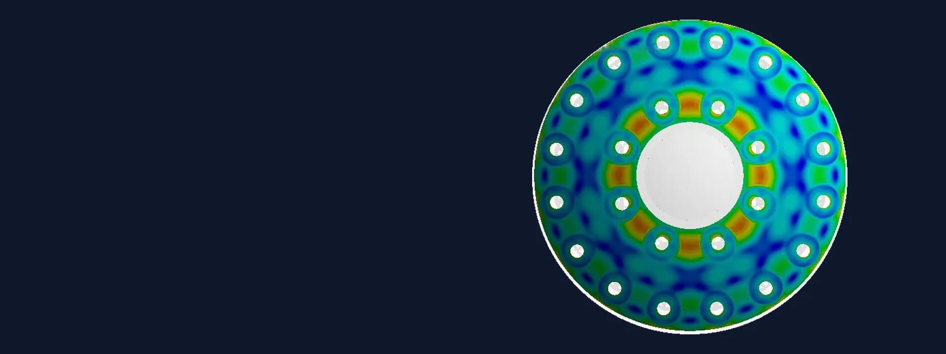
Thermal Stress Design-by-Analysis of a Third-Stage Separator Plenum to ASME VIII Div 2
Thermal stress design-by-analysis of a refractory-lined third-stage separator head and plenum to ASME VIII Div 2, with seismic and creep checks.
Project brief
An equipment supplier was building a third-stage separator for a refinery project. The vessel is refractory lined and carries a plenum chamber hung from its top head, with a large set of cyclones suspended below the plenum floor. Hot flue gas runs through the cyclones while the outer shell stays much cooler, so the head to plenum junction and the stainless to carbon steel skirt welds sit across a steep temperature gradient. The EPC reviewer wanted these details proven by analysis before fabrication.
Shirsh Technosolutions carried out the thermal stress design-by-analysis in ANSYS Mechanical. We combined heat transfer through the lining with pressure, weight, seismic and creep checks, and answered the reviewer's comments until the package was complete.
What was at risk
Normal rule-based formulas cover shells and heads under pressure. They do not cover a hot plenum skirt welded into a cooler head, or a bimetallic weld halfway down a skirt that is hot at one end and close to ambient at the other. In this geometry the thermal stress is the largest part of the total, and it changes with the weather outside. A hot still day and a cold windy one give two quite different temperature fields.
The design also had to carry the cyclone weight in an emergency flooded condition, the pressure difference across the plenum and a seismic load at the cyclone set. The stainless steel internals run in the creep range, so a plain elastic check against room temperature allowables would not be enough. Later the reviewer asked for the creep assessment in detail, for the skirt results under cold weather with seismic load, and for the temperature at the dissimilar metal weld on the gas outlet nozzle.
Solution offered
Heat transfer through the lining. We built an axisymmetric model of the head, the outlet nozzle, the plenum skirts and floor, with the refractory and insulation layers modelled explicitly. Hot and cold weather boundary conditions covered internal gas heat transfer and convection and radiation to ambient outside, using temperature dependent properties. This gave upper and lower bounds on the temperature field.
Elastic stress analysis with imported temperatures. The temperature fields were carried into the structural model by sub-modelling and combined with design pressure, the plenum pressure difference, self-weight and cyclone weight for the normal operating and emergency flooded cases. The refined mesh at the head junction, the skirt taper and the bimetallic welds captured the stress gradients.
ASME VIII Div 2 Part 5 evaluation. Stresses were linearised through the thickness at sections across the critical areas, classified, and checked against their Part 5 limits using allowables from ASME Section II Part D. Where the primary plus secondary range went above the elastic limit at the skirt welds and junction, the simplified elastic-plastic method of Part 5 was applied.
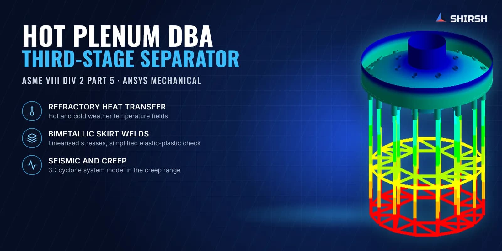
3D cyclone system model for seismic and creep. A second model used shell elements for the head, plenum and supports and beam elements for the cyclones, diplegs and bracing. The temperature field was mapped onto it. Seismic load was applied at the cyclone set, and creep range allowables for the stainless internals were set from the expected hours at each operating condition.
Design changes and reviewer comments. The first results showed that the outer skirt stub at the head junction needed more thickness, and the supplier revised the skirt drawings to our recommendation before the final run. We then added the cold weather seismic results, the creep evaluation and a separate thermal model of the outlet nozzle to report the temperature at its dissimilar metal weld.
Common questions
Why is thermal stress analysis needed for a refractory-lined separator vessel? The internals run close to the hot gas temperature while the shell stays much cooler. Where hot skirts weld into the cooler head, the temperature gradient creates thermal stress that rule-based design does not cover, so ASME VIII Div 2 Part 5 design-by-analysis is used.
What is the simplified elastic-plastic analysis in ASME VIII Div 2? When the elastic primary plus secondary stress range at a location exceeds its limit, Part 5 allows a simplified elastic-plastic check. The range is rechecked without the thermal bending part, and the thermal stress is checked separately against a ratcheting limit, so a local thermal peak does not fail an otherwise sound design.
Challenges we overcame
Steep temperature gradient between hot stainless internals and the cooler carbon steel head
Bimetallic welds in the plenum skirts where thermal stress dominates the total
Hot and cold weather conditions giving two different temperature fields to evaluate
Stainless steel cyclone internals operating in the creep range
Emergency flooded cyclone weight combined with seismic load at the cyclone set
Several rounds of EPC reviewer comments, including creep, cold weather seismic and nozzle weld temperature
How we executed
- 1
Built an axisymmetric model of the head, nozzle, plenum skirts and floor with refractory and insulation layers
- 2
Ran steady-state heat transfer for hot and cold weather conditions
- 3
Imported the temperature fields into the structural model by sub-modelling
- 4
Applied design pressure, plenum pressure difference, self-weight and cyclone weight for normal and flooded cases
- 5
Linearised stresses at the critical sections and checked them against ASME VIII Div 2 Part 5 limits
- 6
Applied the simplified elastic-plastic method where the elastic stress range went above its limit
- 7
Built a 3D shell and beam model of the cyclone system for seismic load and creep range checks
- 8
Added a thermal model of the outlet nozzle to report the dissimilar metal weld temperature
Project outcome
The head to plenum junctions and the bimetallic skirt welds were shown acceptable to ASME VIII Div 2 Part 5 for all hot and cold weather cases.
Where elastic results exceeded the limit, the simplified elastic-plastic check confirmed the design, including the seismic cases.
The cyclone hangers, plenum floor, bracing and other internals stayed within their creep range allowables.
The outer skirt stub at the head junction was thickened on our recommendation before fabrication.
The supplier received a complete design-by-analysis package that answered each of the reviewer's comments.
Project gallery
Where this lives
At a glance
We apply the same rigour to every engagement
Let us show you what's possible for your product.