
CFD of Mixing and Heat Transfer in a Jacketed Agitated Reactor
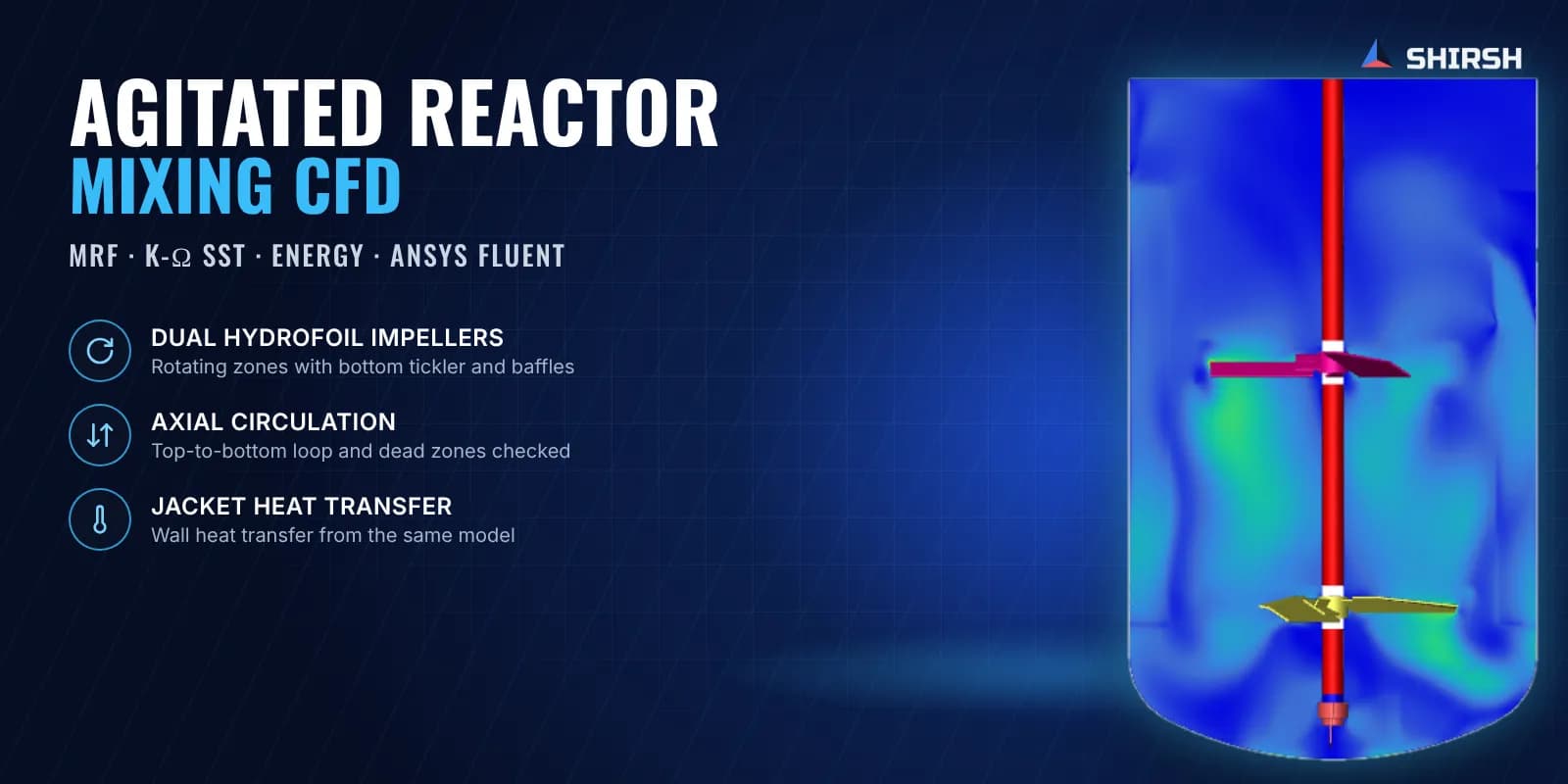
MRF CFD of a jacketed reactor with dual hydrofoil impellers and a bottom tickler, checking circulation, dead zones and wall heat transfer before fabrication.
Project brief
A process equipment fabricator was building agitated reactors in several capacities and wanted to know that the agitator design would actually mix the batch and heat it evenly. Each reactor has two hydrofoil impellers on a common shaft, a small tickler blade in the bottom dish and wall baffles, with heating through a jacket.
Shirsh Technosolutions modelled the reactor in ANSYS Fluent to show the flow pattern the agitator produces and how well heat moves from the jacketed wall into the batch, before the vessel went into fabrication.
What was at risk
Hydrofoil impellers are chosen for strong axial pumping at modest power. In a tall vessel with two of them, though, the flows from the upper and lower impeller can work against each other or leave slow regions in between. The bottom dish is another weak spot, where poor movement leads to settling and cold spots near the outlet.
Heating adds one more question. The jacket can transfer heat only if the liquid next to the wall keeps moving, so mixing and heat transfer had to be judged together in one model.
Solution offered
We built the fluid volume of the reactor with the vessel, both hydrofoil impellers, the bottom tickler and the baffles, simplifying only details that do not affect the flow. It was meshed with poly-hexcore cells and prism layers on the walls and blades.
Impeller rotation was modelled with the steady-state multiple reference frame (MRF) method, with rotating zones around each impeller and the rest of the tank stationary. Turbulence was solved with the k-ω SST model, picked because it handles near-wall flow well and gives a dependable wall heat transfer coefficient. The energy equation was switched on, with the jacket represented as a heated wall.
We reviewed velocity contours and vectors on vertical and horizontal planes and at each impeller, and extracted impeller pumping, power draw, average velocity and wall heat transfer coefficient, so the client could judge the design on numbers as well as pictures.
Common questions
Why MRF and not a sliding mesh? For a baffled tank in steady operation, MRF gives the time-averaged flow and heat transfer at a fraction of the cost of a transient sliding mesh run. Sliding mesh is kept for cases where the impeller and baffle interaction in time really matters.
What does the bottom tickler do? It keeps the liquid moving in the bottom dish, below the reach of the main impellers, so solids do not settle and the bottom does not run colder than the rest of the batch.
Challenges we overcame
Two impellers on one shaft whose flows can interfere
Slow regions in the bottom dish and between the impellers
Judging mixing and jacket heat transfer together
Near-wall resolution good enough for the heat transfer coefficient
Modelling rotating parts at a reasonable cost for a design check
How we executed
- 1
Built the fluid volume with vessel, hydrofoil impellers, bottom tickler and baffles
- 2
Meshed with poly-hexcore cells and prism layers on walls and blades
- 3
Set rotating MRF zones around each impeller
- 4
Solved steady RANS with k-ω SST and the energy equation, with the jacket as a heated wall
- 5
Plotted velocity contours and vectors on vertical, horizontal and impeller planes
- 6
Checked the bulk volume for low-velocity and dead zones
- 7
Extracted pumping, power draw, average velocity and wall heat transfer coefficient
- 8
Issued the report with the reactor general arrangement drawing
Project outcome
The hydrofoils set up strong axial flow: down along the shaft, across the bottom dish and back up along the walls.
High-velocity regions reach the tank walls, so the whole batch is kept moving and stratification is avoided.
Low-velocity regions in the bulk are minimal, and the tickler keeps the bottom dish agitated, preventing cold spots.
Turbulence at the wall supports efficient heat transfer from the jacket into the batch.
The client had a flow and heat transfer basis for the agitator design ahead of fabrication.
Project gallery
Where this lives
At a glance
We apply the same rigour to every engagement
Let us show you what's possible for your product.