BESS Container CFD and Structural FEA: Cooling Airflow, Wind and Seismic Checks
CFD of cooling airflow around battery racks and FEA of the container for wind and seismic loads, so a BESS integrator could fix its layout early.
Project brief
A battery energy storage system integrator was packing lithium-ion battery racks, HVAC units, an energy management panel and a fire suppression system into compact steel containers for grid and industrial sites. Before the containers were built, its engineering team wanted to know two things: whether the HVAC air would actually reach and cool every battery module, and whether the container itself would stand up to site wind and earthquake loads with all that equipment inside.
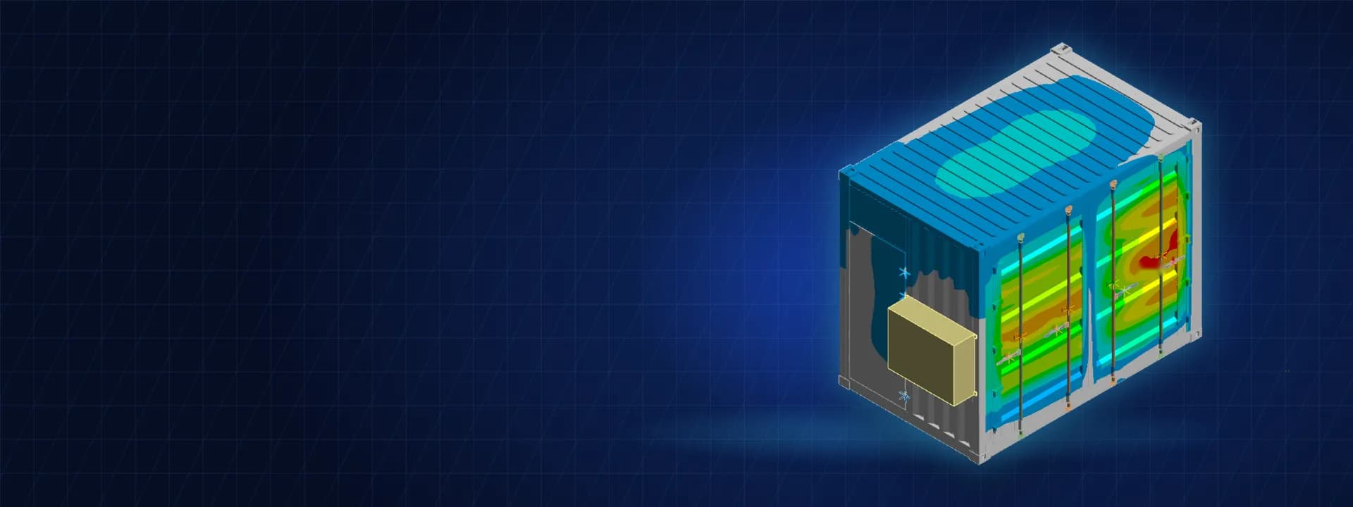
Shirsh Technosolutions answered both with simulation. A CFD model in ANSYS Fluent showed how the cooling air moves through the racks and what temperatures the batteries settle at, and a structural FEA in ANSYS Mechanical checked the container shell, frame and equipment mounts for wind to IS 875 Part 3 and seismic loads to IS 1893 Part 1. The study picked up one wall that needed extra support, so the fix went into the design and not onto site.
What was at risk
A BESS container is a crowded box. The battery racks give off heat all the time, the HVAC units blow conditioned air in from one side, and the exhaust has to take the warm air out without short-circuiting the supply. If the air finds an easy path around the racks, some modules run hotter than others, which shortens battery life and raises safety concerns.
The same container also has to behave as a structure. It sits on a few ground supports, carries heavy racks and wall-mounted HVAC units, and takes wind on its large flat sides and shaking during an earthquake.
The integrator needed clear answers:
how the HVAC supply air distributes through and around the battery racks
what temperature the racks reach and whether it is even from one rack to the next
whether the shell, frame and floor stay within allowable stress under wind and seismic loads with all equipment in place
whether any wall or panel deflects more than the code allows
It also asked for a second structural run with heavier battery racks, so the container would not limit its choice of battery supplier.
Solution offered
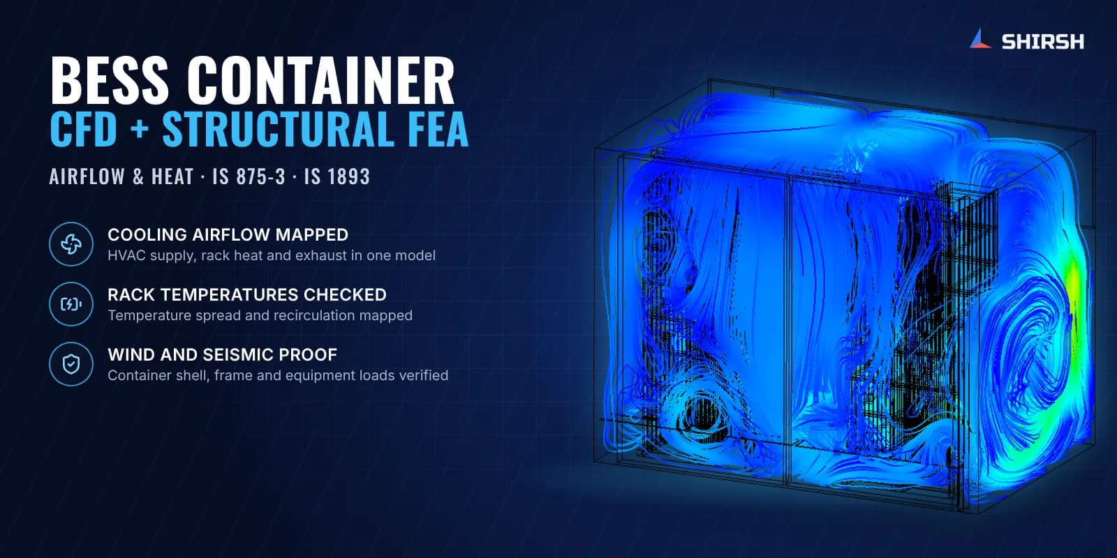
Cooling airflow by CFD. We built a three-dimensional CFD model of the container interior in ANSYS Fluent with the battery racks, the HVAC supply inlets, the exhaust openings, the fire suppression unit and the auxiliary panels.
Each battery module modelled with its own heat source and module fan, so the heat comes from where it really is.
HVAC supply flow and temperature taken from the unit data, with the racks treated as steel structures.
Steady-state turbulent flow solved with the k-ω SST model on a poly-hexcore mesh, with mesh quality held above the usual limits.
Temperature and velocity read on several planes through the racks, from the top and as 3D streamlines, so the team could see exactly where the air goes.
Structural FEA of the loaded container. The container was modelled in ANSYS Mechanical with shell and solid elements: corrugated walls, roof, frame members, floor channels, doors and the ground supports. The racks, HVAC units, fire suppression system, energy management panel and AC distribution board were applied at their real locations as equipment masses, taking the heaviest case so the check stays conservative.
Self-weight with all equipment in place.
Wind pressure built up to IS 875 Part 3 and applied from both directions on the long sides.
Seismic loads to IS 1893 Part 1 using modal analysis with pre-stress, in both horizontal directions.
Stresses checked against yield with a factor of safety of 1.5, and wall deflections against the IS 800 limit.
Same method, a second container. For a larger container from the same integrator, we repeated the wind-load FEA to IS 875 Part 3 at its own site wind speed, with its own rack, HVAC and electrical equipment loads.
Common questions
Why use CFD for a BESS container when the HVAC is already sized for the heat load? Sizing matches total cooling to total heat. It does not show whether the air reaches every module. CFD shows the actual flow path, the recirculation zones and the temperature of each rack, so supply and exhaust positions can be set before the container is built.
What structural checks does a BESS container need? At minimum self-weight with all equipment, wind on the walls and roof, and seismic loads for the site, together with a deflection check on the walls that carry heavy units such as HVAC. FEA covers all of these on the real container geometry, including local effects at mounts and supports that hand calculations miss.
Challenges we overcame
Heat released by many battery modules packed close together in a small enclosure
HVAC supply and exhaust that could short-circuit and bypass the racks
Heavy racks and wall-mounted HVAC units on a thin-walled steel container
Wind on large flat walls and seismic shaking acting on the same structure
A heavier battery rack option that had to be covered without redesigning the container
Two container sizes checked with one consistent method
How we executed
- 1
Collected the container 3D model, rack layout, HVAC and equipment data and heat loads from the client
- 2
Built the CFD model of the container interior with racks, battery modules, HVAC inlets and exhaust in ANSYS Fluent
- 3
Solved steady-state turbulent airflow and heat transfer with the k-ω SST model
- 4
Reviewed temperature and velocity on planes through the racks, from the top and as 3D streamlines
- 5
Built the structural model of the loaded container in ANSYS Mechanical with shell and solid elements
- 6
Applied self-weight, IS 875 Part 3 wind pressure and IS 1893 Part 1 seismic loads with all equipment masses
- 7
Checked stresses against yield with a factor of safety and wall deflections against IS 800
- 8
Re-ran the structure with heavier battery racks and checked a second, larger container for wind load
Project outcome
The CFD showed an even temperature spread across the battery racks, with the HVAC air reaching both racks and the warm air leaving through the exhaust.
Stresses in the shell, frame and supports stayed within the allowable limit under self-weight, wind and seismic loads.
The wall carrying the HVAC units deflected more than the IS 800 limit allows, and added supports on that side were recommended before fabrication.
The heavier battery rack option was checked as well, and the larger container was found safe for its site wind load.
Project gallery
Where this lives
At a glance
We apply the same rigour to every engagement
Let us show you what's possible for your product.