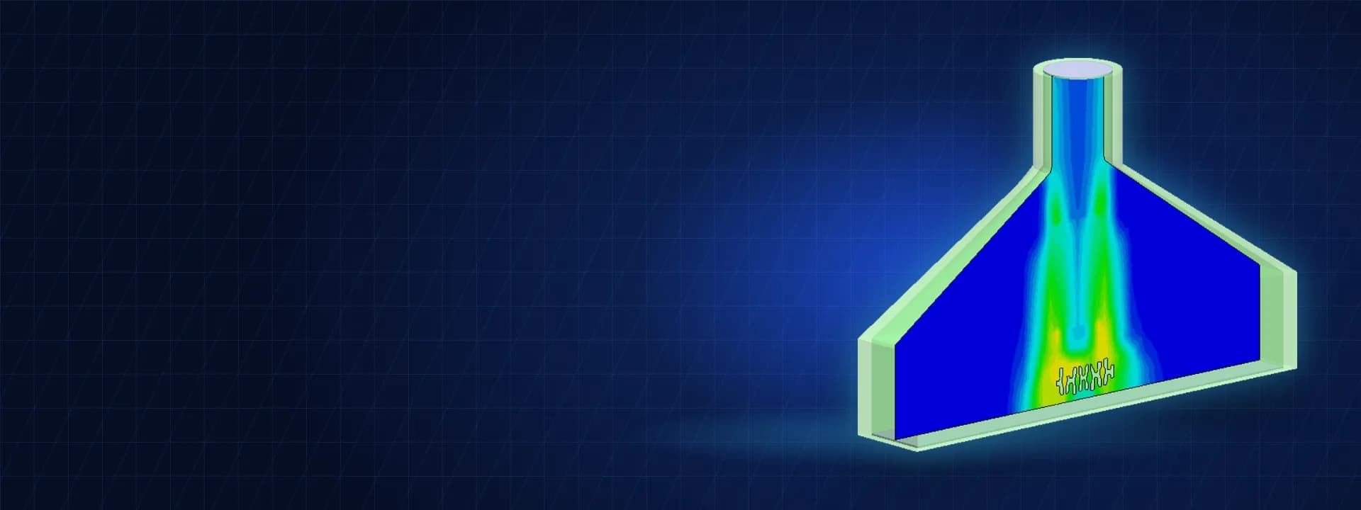
Transient CFD of a Controlled Cooling Conveyor for Hot Steel Castings
Transient CFD of a casting cooling conveyor: blower jets and casting temperature tracked zone by zone to size the blowers before the line was built.
Project brief
An engineering company was designing a controlled cooling conveyor for hot steel castings. The castings leave the process very hot and have to cool along a set curve, fast enough to keep the line moving but in stages, so the metallurgy comes out right. Cooling is done by a row of blower hoods over the conveyor, followed by a chiller zone.
The client had sized the blowers by hand and wanted to know whether that layout would really bring the castings down the way the curve demanded. Shirsh Technosolutions built a transient CFD model of the castings moving through each blower zone, tracked their temperature zone by zone and showed how the air from each hood actually reached them. The first run exposed a shortfall, and the revised layout was checked the same way before anything was fabricated.
What was at risk
A cooling conveyor looks simple on paper: count the blowers, pick a flow rate and a hood size, and the castings cool. In practice the result depends on how the air jet spreads inside each hood, how much of it reaches the casting surface and how long the casting stays under it at the line speed.
The client needed answers to a few practical questions:
what temperature a casting reaches as it leaves each blower zone
whether the planned number of blowers is enough to bring it down to the target before the chiller
whether the air from each hood covers the casting properly or bypasses part of it
Halfway through, the end customer changed the casting, the inlet conditions and the blower specification, so the model had to be updated quickly and run again on the new inputs.
Solution offered
A moving casting, not a steady snapshot. We modelled one blower hood at a time with the casting on the conveyor below it, and ran a transient conjugate heat transfer analysis for the time the casting spends in that zone at the line speed. The casting temperature at the exit of one zone became the starting condition for the next, so the cooling curve along the whole conveyor was built up zone by zone.
Hood, duct, canopy, casting and conveyor modelled from the client's general arrangement and 3D model.
Blower volume flow and pressure at each hood inlet, ambient air temperature as given, and suction to atmosphere.
Heat transfer by conduction inside the casting and convection to the moving air, solved together.
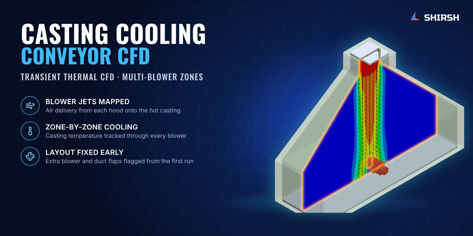
Air velocity, flow trajectories and turbulence plotted inside each hood to see where the jet actually goes.
First run: a clear shortfall. With the original blower layout the casting was still far too hot after the last blower, and the flow plots showed the jet from the hood was not covering the whole region over the casting. We recommended adding a fifth blower and fitting flaps in the duct so the air spreads across the hood.
Second run on the revised design. The client came back with a revised specification, including five blowers at a higher flow rate. We re-ran every zone on the new inputs and reported the casting temperature after each blower, the flow pattern and the boundary conditions used, so the design team could compare the result directly against its target cooling curve.
Common questions
Why use CFD to size blowers on a casting cooling conveyor? A hand calculation assumes the air reaches the casting evenly. CFD shows where the jet really goes inside the hood, how much of the casting it covers and how fast the casting cools in each zone, so blower count, flow and ducting can be fixed before the line is built.
Why model the cooling zone by zone? The casting keeps moving, and its temperature on leaving one blower is what the next blower has to work with. Chaining transient runs zone by zone follows that history, which is what decides whether the casting meets its cooling curve.
Challenges we overcame
Hot steel castings that must follow a staged cooling curve
A moving casting that spends only a short time under each blower
Air jets that may not cover the whole hood area
A blower layout sized by hand that needed checking before fabrication
Inputs from the end customer that changed partway through the job
A quick re-run of every zone on the revised design
How we executed
- 1
Collected the conveyor general arrangement, 3D model, casting data and target cooling curve from the client
- 2
Built the CFD model of a blower hood, duct, canopy, casting and conveyor
- 3
Set the blower flow and pressure, ambient air temperature and suction boundary
- 4
Ran a transient conjugate heat transfer analysis for the time the casting spends in each zone
- 5
Carried the casting temperature from one zone into the next to build the cooling curve along the line
- 6
Plotted air velocity, trajectories and turbulence to check how the jet covers the casting
- 7
Recommended an additional blower and duct flaps after the first run
- 8
Re-ran all zones on the revised five-blower specification and reported the temperature after each blower
Project outcome
The first CFD run showed the original blower layout would leave the castings too hot after the last blower.
Flow plots showed the air jet was not covering the full hood area, and duct flaps were recommended to spread it.
An additional blower was recommended, and the revised design with five blowers was checked zone by zone.
The client received the casting temperature after every blower and the flow pattern in each hood, to compare against its target cooling curve before fabrication.
Project gallery
Where this lives
Software used
Industries
At a glance
We apply the same rigour to every engagement
Let us show you what's possible for your product.