Transient Thermal Analysis of an FCC Catalyst Cooling Silo and Hopper
Transient thermal FEA of a refinery FCC catalyst cooling silo and hopper, with conduction, convection and radiation, to size natural and air-pad cooling.
Project brief
An engineering company supplying catalyst-handling equipment for a refinery's fluid catalytic cracking (FCC) unit needed to know how quickly spent catalyst would cool once it left the process. The catalyst arrives very hot, collects in a cooling silo and is then discharged to a catalyst hopper where it is held for several days before disposal. Both vessels had to be designed around realistic temperatures, and the client wanted to know whether extra cooling air would be needed in the hopper.
Shirsh Technosolutions carried out a transient thermal analysis of the catalyst cooling silo and the catalyst hopper. We modelled heat flow by conduction through the catalyst bed and the steel shell, natural convection and radiation from the outer surface, and the effect of injecting cooling air through air pads in the hopper cone.
What was at risk
Hot catalyst in a silo does not cool evenly. The bed is thick, the shell loses heat only through its outer surface, and the silo keeps filling, so fresh hot catalyst lands on layers that are already cooling. The temperature leaving the bottom of the silo, which becomes the starting point for the hopper, cannot be found from a single steady-state calculation.
Surface heat loss is also not constant. Natural convection and radiation both depend strongly on the shell temperature, so a fixed film coefficient would either overstate or understate cooling over the cycle.
The client needed:
the temperature history of the catalyst in the cooling silo as it fills and cools
a realistic discharge temperature to use for the hopper design
a comparison of natural cooling in the hopper against injecting cooling air through one or two air pads
Solution offered
Axisymmetric transient thermal model. Both vessels are bodies of revolution, so we built 2D axisymmetric finite element models of the silo and the hopper with the catalyst bed and the steel shell. This kept the mesh fine through the bed while allowing long transient runs at modest cost.
All three heat transfer paths. Conduction through the catalyst and the shell followed Fourier's law, with bulk density, thermal conductivity and specific heat assigned separately to the catalyst and to the steel. Natural convection from the shell used a film coefficient that varies with surface temperature, and radiation used the Stefan-Boltzmann law with an emissivity for oxidised steel. The governing equation was solved in the time domain, so the heat stored in the bed is captured as it cools.
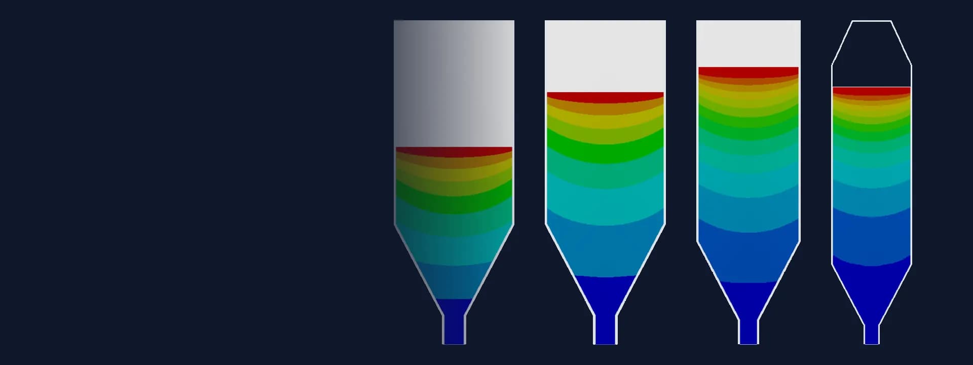
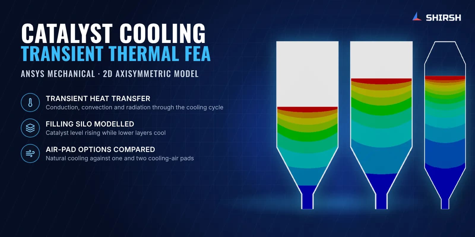
Silo filling and cooling. The silo model was run through the filling and cooling period with the catalyst level rising over time. Temperature contours at successive time steps showed how each new charge of hot catalyst sits above layers that are already cooling, and where the coolest catalyst collects near the outlet. From these results we set a conservative discharge temperature as the starting condition for the hopper.
Hopper cooling options. Three hopper cases were compared: natural cooling only, cooling air injected through one air pad at the bottom of the cone, and air injected through two air pads at the bottom and the side. For each case we tracked the bed temperature along with the heat removed by convection and by radiation over time.
Clear direction for the design. With natural cooling alone a hot core stayed in the middle of the hopper bed. Air injection cooled the bed much faster, and the two-pad arrangement brought the whole bed close to ambient within the simulated period, giving the client a sound basis for specifying the hopper cooling arrangement.
Common questions
Why use transient thermal analysis for a catalyst cooling silo? The catalyst bed stores a large amount of heat and the silo keeps filling, so temperatures change with time and position. A transient analysis follows that history and gives the actual discharge temperature, which a steady-state calculation cannot.
How do convection and radiation enter a thermal FEA of a hot vessel? Both are applied as surface boundary conditions on the outer shell. Convection uses a film coefficient that rises with surface temperature, and radiation uses the Stefan-Boltzmann law with the shell emissivity, so heat loss is highest when the vessel is hottest and falls as it cools.
Challenges we overcame
A thick catalyst bed that stores heat and cools very unevenly
A silo that keeps filling, so hot catalyst lands on cooling layers
Surface heat loss by convection and radiation that changes with shell temperature
A hopper starting temperature that depended on the silo result
Comparing natural cooling against air injection before the hopper design was fixed
How we executed
- 1
Reviewed the silo and hopper geometry and the catalyst fill levels over the cooling cycle
- 2
Built 2D axisymmetric finite element models of the catalyst bed and steel shell
- 3
Assigned separate thermal properties to the catalyst and the steel
- 4
Applied temperature-dependent natural convection and radiation on the outer shell
- 5
Solved the transient silo case through filling and cooling and reviewed temperatures at successive times
- 6
Set a conservative discharge temperature from the silo results as the hopper starting condition
- 7
Ran the hopper with natural cooling, one air pad and two air pads
- 8
Compared bed temperatures and heat removed by convection and radiation for each option
Project outcome
The temperature history of the catalyst in the cooling silo was mapped through filling and cooling.
A realistic, conservative catalyst discharge temperature was set for the hopper design.
Natural cooling alone was shown to leave a hot core in the middle of the hopper bed.
Cooling air through two air pads at the bottom and side of the cone brought the hopper bed close to ambient within the simulated period.
Project gallery
Where this lives
Software used
Related solutions
Industries
At a glance
We apply the same rigour to every engagement
Let us show you what's possible for your product.