Wind Load Engineering for Masts, Solar and Exposed Structures
Wind loads to IS 875 Part 3 and ASCE 7, backed by CFD where the code runs out, for masts, solar arrays, canopies, stacks and towers.
What this solution covers
For tall, light or unusually shaped structures, wind usually governs the design. Shirsh Technosolutions works out wind loads from the code, IS 875 Part 3 or ASCE 7, and where the shape or layout falls outside the code tables we use CFD in ANSYS Fluent to find the pressures directly.
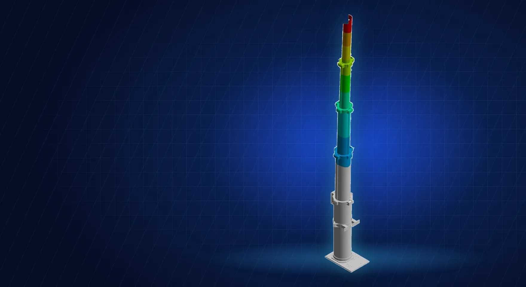
Those loads then go into a structural model in ANSYS Mechanical, so the client gets stress, deflection and support reactions for members and foundations from one study. We work on telescopic and lattice masts, rooftop and ground-mount solar arrays, carport canopies, stacks and equipment enclosures.
Pain points we address
Shapes, layouts or arrays not covered by the code's pressure coefficient tables
Conservative assumptions adding steel and cost to every structure
Masts and poles deflecting too much for the equipment they carry
Foundation and fixing designers waiting on support reactions
Indian and overseas customers asking for different wind codes
What we solve
Design wind speeds and pressures to IS 875 Part 3 and ASCE 7
CFD of wind over arrays, canopies and buildings to obtain pressure coefficients
Structural FEA of masts, frames and supports under wind from several directions
Deflection checks for payloads such as antennas and cameras
Base plate, clamp and anchor reactions for foundation design
Comparison of code and CFD loads to strip out unnecessary conservatism
How we approach it
- 1
Collect site data, terrain category, structure class and the governing code
- 2
Convert wind speed to design pressure and force for each direction
- 3
Where the code is silent, run CFD with an atmospheric boundary layer profile at the inlet
- 4
Map the pressures onto a structural model of the members and joints
- 5
Solve for stress, deflection and reactions in every wind direction and load level
- 6
Report the loads in a form foundation and connection designers can use directly
Deliverables
Wind load calculation to the governing code
CFD report with pressure distributions and coefficients, where CFD is used
Structural FEA report with stress, deflection and reactions
Load tables per wind direction
Recommendations to lighten or stiffen the structure
Expected outcomes
Wind loads based on the actual geometry, not the nearest table
Structures sized for the load they will see, with less wasted steel
Stress and deflection checked for every wind direction
Reactions ready for foundation and fixing design
Why Shirsh
We have worked on wind loading of solar structures in India for years and have published our own review of how IS 875 is applied to them. That experience tells us where the code is conservative, where it is silent and when a CFD study will actually change the answer, so the client pays for CFD only when it earns its place.
Where this lives
Industries served
Software used
Related case studies
Wind Load FEA of a Telescopic Communications Mast to IS 875 Part 3
Static FEA of a telescopic communications mast in two payload variants, under operational and survival wind from three directions to IS 875 Part 3.
ReadCFD Analysis of Wind Loading on Rooftop Solar PV Arrays
Rooftop solar wind CFD comparing building layouts and array sizes, giving pressure data on both panel faces for structural design.
ReadFloating Solar Engineering: CFD Wind Loads and Hydrostatic Buoyancy FEA of Panels and Floats
Floating solar engineering: CFD wind loads on every panel and float in ANSYS Fluent, plus hydrostatic buoyancy, draft and float response by FEA.
ReadWant to learn this?
We also offer ANSYS & SolidWorks training courses.
At a glance
Discuss your project with our engineers
Tell us about your simulation, validation or design challenge.