Floating Solar Engineering: CFD Wind Loads and Hydrostatic Buoyancy FEA of Panels and Floats
Floating solar engineering: CFD wind loads on every panel and float in ANSYS Fluent, plus hydrostatic buoyancy, draft and float response by FEA.
Project brief
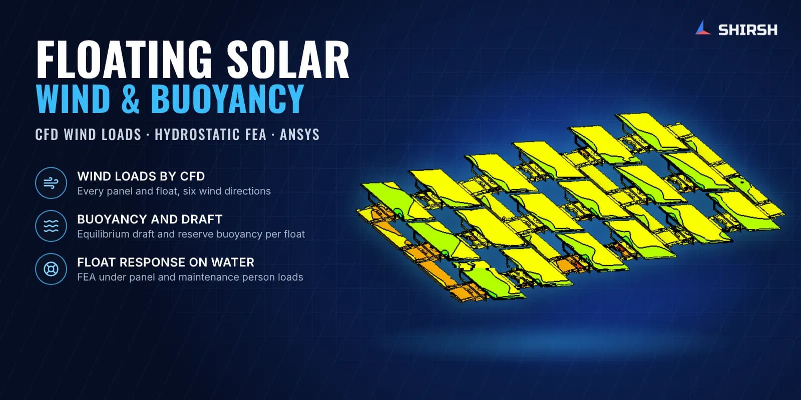
A floating solar plant has to deal with two fluids at once. Wind pushes on the tilted panels and tries to lift and drag the block, while the water underneath has to carry the panels, the floats and the people who walk on them for cleaning and maintenance. Shirsh Technosolutions has worked on both sides of this problem for floating solar companies, and this case study brings two of those projects together.
In the first, a floating solar system developer asked us for a CFD wind load study of its float and panel block in ANSYS Fluent. We gave forces and moments on every panel and float for six wind directions, with the panel loads separated from the float loads. In the second, a float manufacturer developing a new range of HDPE floats asked us to check the hydrostatic response of each float and of assembled float blocks: buoyancy, draft, reserve buoyancy and how the floats sink and tilt under panel and person loads, using hand calculations and FEA in ANSYS Mechanical.
What was at risk
Wind on a floating array does not behave like wind on a ground-mount plant. The panels sit low over the water at a small tilt, front rows take the wind head-on and inner rows sit partly in the wake of the panels ahead. The developer needed loads at every panel position, and for its fixing design it needed the local forces and moments on the panel alone, separated from the main float under it. The global loads on the block also feed the mooring design, where the hydrodynamic response of the anchored array is worked out, so they had to be complete for every wind direction.
On the water side, a float has to carry the panel with a sensible draft and still keep enough buoyancy in reserve. The float maker was launching new float shapes for two module sizes, including large walkway floats that maintenance staff stand on. It needed to know how deep each float sits, how much load it can take before it goes under, and how a connected block of floats sinks and tilts when a person stands at different places on it. A simple displaced-volume calculation gives the average draft, but it does not show local dipping of a long, flexible plastic float.
Solution offered
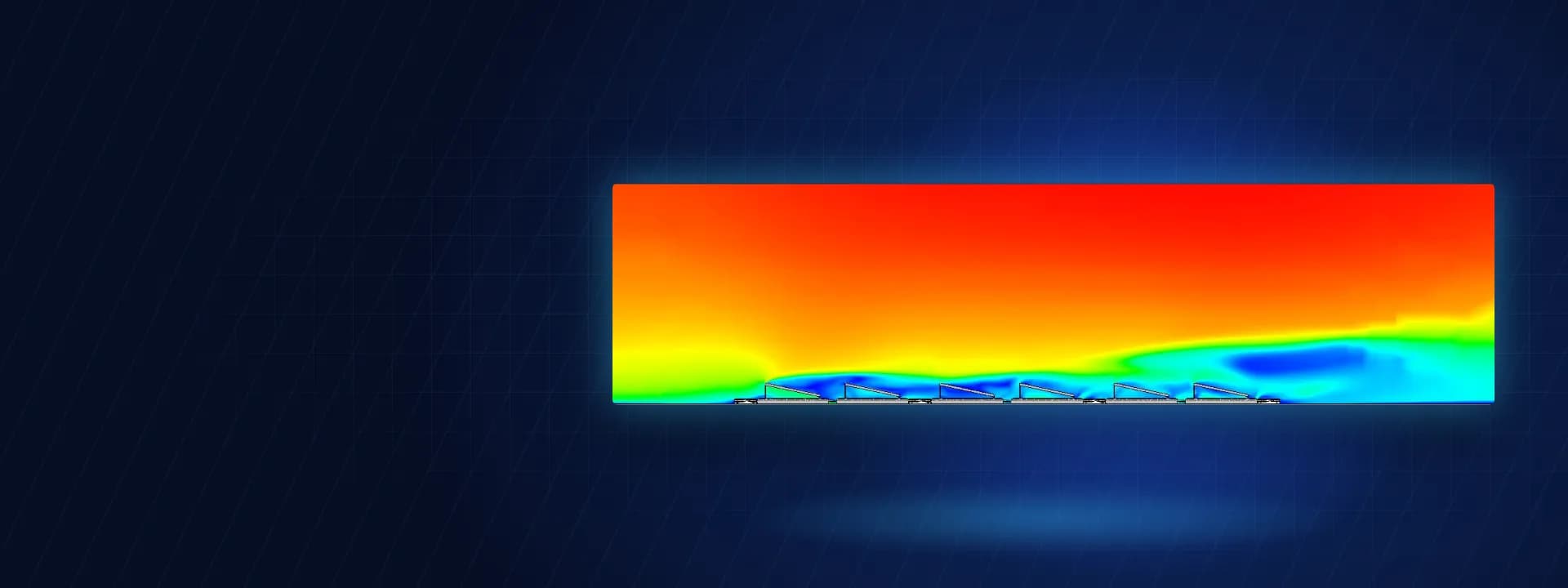
Wind loads by CFD. We built a large air domain around the floating block and subtracted the panel and float geometry from it. Small float details were simplified after discussion with the client, and before the main runs we compared the main float with and without its ridge detail in two wind directions so the client could see the effect before agreeing the geometry. As in the client's own method, the water surface was treated as a rigid floor.
Steady, incompressible, turbulent flow in ANSYS Fluent with the realizable k-epsilon model and enhanced wall treatment, with wall y+ checked along the panels and floats.
An atmospheric wind profile at the inlet based on the one-seventh power law, a pressure outlet and symmetry on the side walls.
A polyhedral and hex-core mesh refined around the panels, frames and floats.
The model was run for six wind directions, from wind on the panel faces to wind from behind them. For each direction we extracted forces on the panel plus main float, the panel alone, the main float and the side floats, row by row, and local forces and moments on each panel in a panel-fixed axis system. After the client's CFD engineer reviewed the first issue, we separated the panel and main float results and added Excel load tables.
Hydrostatics and float response by FEA. For every float in the new range (main, secondary and auxiliary walkway floats) we first ran a buoyancy balance. The weight of the float, the module and a maintenance person's live load was set against the water displaced, giving the equilibrium draft. A second check with the float fully submerged gave the maximum buoyancy force, which shows the reserve the float has before it goes under.
We then modelled the floats in ANSYS Mechanical with the water represented as an elastic support under the float, so the analysis shows how the float trims and where it dips, not just its average draft. The same approach was applied to a connected block of main floats carrying panels, with a maintenance person placed at different positions, and to auxiliary walkway float layouts loaded at different points. Each case was reported against the water line.
Common questions
What is the difference between hydrostatic and hydrodynamic checks for floating solar? Hydrostatic checks look at the floats at rest: buoyancy, draft, reserve buoyancy and how far they sink under panels and people. Hydrodynamic checks look at the array moving on the water under wind, waves and current, mainly for mooring and connection design. Wind loads from CFD are one of the main inputs to the hydrodynamic and mooring work.
Why use FEA for float buoyancy instead of a simple calculation? A displaced-volume calculation gives the average draft of a float. Plastic floats are flexible, so a long float or a walkway can dip locally under a person's weight. FEA with the water as an elastic support shows that local sinking and tilt, which a hand calculation cannot.
Challenges we overcame
Wind loads on a low, tilted floating array that no ground-mount code covers directly
Inner rows partly sheltered by the panels ahead, so every position needed its own load
Separating local loads on the panel from loads on the float under it
Draft and reserve buoyancy for a whole new range of float shapes
Local dipping of long, flexible walkway floats under a maintenance person's weight
Delivering loads and results in each client's own axis system and format
How we executed
- 1
Reviewed each client's design, CAD models, module weights and required outputs
- 2
Simplified the floating block geometry and checked the effect of the float ridge detail on the wind flow
- 3
Built the CFD domain and refined mesh, and solved six wind directions in ANSYS Fluent
- 4
Extracted global and panel-only forces and moments for every panel and float position
- 5
Ran a buoyancy balance for each float under self weight, module and person load to get the draft
- 6
Checked reserve buoyancy with each float fully submerged
- 7
Modelled single floats and float blocks on an elastic water support in ANSYS Mechanical under panel and person loads
- 8
Issued CFD and hydrostatic FEA reports with contours, load tables and water-line plots
Project outcome
The developer received forces and moments for each panel and float position in all six wind directions, ready for its fixing and mooring design.
Wind from behind the tilted panels gave clearly higher panel loads and moments than head-on wind, while side wind gave the lowest, which shows which cases govern.
The float maker received the draft and reserve buoyancy of every float in its new range, with the float response shown against the water line.
The FEA showed the large walkway floats dipping in the middle under a person's load, which led the maker's team to look at a stiffening recess underneath.
Project gallery
Where this lives
At a glance
We apply the same rigour to every engagement
Let us show you what's possible for your product.