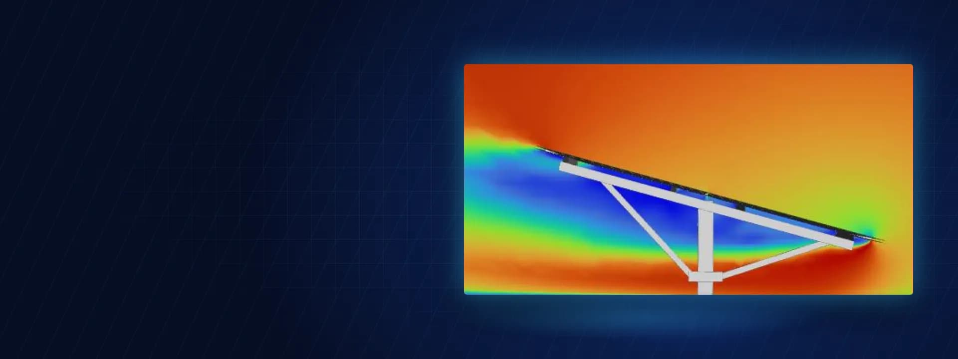
Vortex Shedding Check of a Ground-Mounted Solar Structure with Wind CFD and Modal FEA
Solar structure vortex shedding check with transient CFD in ANSYS Fluent, CFD wind pressures mapped into FEA and a modal study of a fixed-tilt MMS.
Project brief
Long fixed-tilt solar tables look rigid on a drawing, yet they are light, flexible and sit right in the wind. Shirsh Technosolutions carried out a combined CFD and FEA study for a solar developer building a ground-mounted plant, with one clear question behind it: could the wind make this mounting structure vibrate badly through vortex shedding, and would the members hold up under the real wind pressure on the modules?
We answered both in one model chain. Wind CFD in ANSYS Fluent gave the pressure on the modules and members, and a transient run gave the vortex shedding frequency. Those pressures were mapped straight into a structural FEA in ANSYS for stress and deflection checks to IS 800 and IS 801, and a modal analysis gave the natural frequencies of the table so the two could be compared.
What was at risk
Code wind loads give a static pressure coefficient for a tilted panel. They say little about what happens behind the panel, where the flow separates and vortices peel off the leading and trailing edges in turn. If the frequency of that shedding sits close to a natural frequency of the table, the structure can be driven into resonance well below its static capacity. Long thin tables with cold-formed members and light bracing are exactly the kind of structure where this question comes up.
The client asked for the full picture. They wanted a 3D model of the structure, CFD for wind from different directions at the design wind speed for the site, dynamic analysis based on the CFD pressures, stress and strain in every member of the mounting structure, and a vortex shedding check. The member sections had to stay practical for a plant going to site on a tight schedule.
Solution offered
Wind CFD on the full table. We built the table as it stands, with the module rows, rafters, columns and bracing, and placed it in a large external flow domain prepared in ANSYS SpaceClaim.
Poly-hexcore mesh generated in ANSYS Fluent meshing, with inflation layers along the walls to resolve the boundary layer.
Incompressible RANS flow with the k-omega SST turbulence model and a power-law atmospheric velocity profile at the inlet.
Steady-state runs for down-wind, up-wind and side-wind directions to get the pressure on both faces of the modules and on the frame members.
Transient runs for the down-wind and up-wind cases, with monitor points in the wake, to extract the Strouhal number and the vortex shedding frequency.
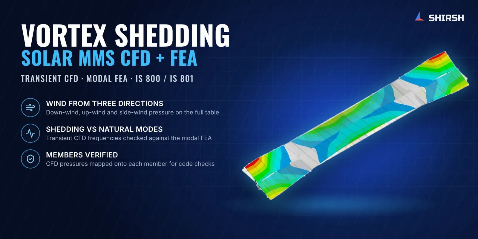
Structural FEA with mapped CFD pressure. The CFD pressure was imported directly onto the module faces and onto each member group (columns, column connectors, rafters, front and rear bracing, hat purlins) in ANSYS Mechanical.
Static structural, nonlinear elastic analysis with bolt elements at the member connections and the modules treated as a stiff mass carried by the purlins.
Dead load with down-wind, up-wind and side-wind load cases set up per IS 800 for serviceability, with the cold-formed member design basis of IS 801 and the steel grades taken from the drawings.
Member deflections checked against span-based limits for the column, rafter cantilever and purlin, and von Mises stress checked against a yield-based allowable for each steel grade.
Force and moment reactions reported at every column support for the foundation designer.
Modal analysis and the shedding check. A modal analysis of the same model, fixed at the column bases, extracted the natural frequencies and mode shapes of the table. The lower modes were compared with the shedding frequencies from the transient CFD to confirm there was no frequency match at the design wind speed.
Common questions
How do you check a solar mounting structure for vortex shedding? Run a transient CFD of the tilted table, read the shedding frequency from the pressure or velocity signal in the wake, and compare it with the natural frequencies from a modal FEA of the same structure. If the shedding frequency stays well clear of the lower natural modes at the design wind speed, resonance from shedding is not a concern.
Why map CFD pressure into the FEA instead of using code pressure coefficients? CFD gives the actual pressure on each module and member for each wind direction, including the uneven load along a long table and the suction on the underside. Mapping it into the FEA puts that real distribution on the structure, so the stresses and deflections reflect how the wind loads the table rather than a uniform average.
Challenges we overcame
A long, light table where wind-induced vibration mattered as much as static strength
Shedding frequency had to come from a transient flow solution, not a code table
Uneven wind pressure along the table and on both faces of the modules
CFD pressure transferred onto every member group of the structure
Cold-formed members of more than one steel grade with bolted joints in one model
A short delivery window set by the plant schedule
How we executed
- 1
Built the 3D model of the fixed-tilt table from the client's general arrangement drawing
- 2
Set up the external flow domain and a poly-hexcore mesh with inflation layers in ANSYS Fluent
- 3
Ran steady-state CFD for down-wind, up-wind and side-wind directions with an atmospheric inlet profile
- 4
Ran transient CFD in the down-wind and up-wind cases and derived the vortex shedding frequency from the Strouhal number
- 5
Mapped the CFD pressure onto the module faces and every member group in ANSYS Mechanical
- 6
Ran nonlinear static FEA for dead load with each wind direction per IS 800 and checked stress and deflection of all members
- 7
Ran modal analysis of the table and compared its natural frequencies with the shedding frequencies
- 8
Reported member results, support reactions and the final member sections to the client
Project outcome
Every member of the mounting structure stayed within its allowable stress and its deflection limit in the governing load cases, and the structure was found satisfactory for its intended service.
The up-wind case governed, and the FEA showed which members worked hardest, with the column closest to its limits while still inside them.
The vortex shedding frequencies from the transient CFD stayed well above the lower natural frequencies of the table, so no resonance from shedding is expected at the design wind speed.
The client received pressure plots for uplift and down-lift, the final member sections, and column support reactions for foundation design, and confirmed completion of the work.
Project gallery
Where this lives
Related insights
Why Fixed-Tilt Ground-Mount Solar Structures Fail
Fixed-tilt ground-mount is the structure everyone treats as solved. No moving parts, a straight load path from module to rail to post to ground, a static wind check, done. That reputation for simplicity is precisely why these structures fail, not from exotic physics, but from foundations pulled out of the soil, connections detailed for the wrong load direction, slender members that buckled under uplift, and corners that saw far more wind than a borrowed coefficient ever admitted. Walk the load path with a failed array in front of you and the causes are rarely mysterious. Here is how to read the damage, and the analysis chain that would have caught it on paper.
ReadHow to Check a Cold-Formed Solar Mounting Structure to IS 801: A Step-by-Step Guide
Most ground-mounted solar structures in India are made from cold-formed steel: thin steel sheet bent into channels and hat sections. Engineers find the wind load from IS 875 Part 3, then check the steel using IS 801. Two mistakes are very common. First, engineers use the full cross-section, but thin steel does not work that way: part of it buckles early, so the code makes you use only the "effective" part. Second, engineers check only the steady (static) load and skip the moving (dynamic) effects. This guide explains both problems in simple steps. It then checks the four main members of a solar structure: post, rafter, bracing, and a 1 mm hat purlin: with full numbers, so you can see exactly where the common shortcuts go wrong.
ReadAt a glance
We apply the same rigour to every engagement
Let us show you what's possible for your product.