
Ground Screw Foundation FEA for a Fixed-Tilt Solar Mounting Structure
Ground screw foundation FEA for a fixed-tilt solar MMS: wind uplift traced from the modules to the screw head in ANSYS, leading to stronger head plates.
Project brief
Ground screws let a solar plant go up without concrete, but the whole table then hangs on a short steel head welded to a helical pile. Shirsh Technosolutions carried out the structural FEA for a manufacturer of ground screw foundations that was supplying a fixed-tilt solar plant. The aim was to show that the screw and its head connection could take the wind uplift coming down from the module table, and to tell the client exactly what to change where they could not.
The work ran in two steps in ANSYS Mechanical. First the ground screw on its own was loaded with the support reactions from the client's structure design. Then the complete fixed-tilt table was modelled on its ground screws, with wind pressure applied on the module faces and the load cases set up per IS 800. Both steps ended with specific design changes to the plates at the screw head, and we also gave the client a note on how to handle tilt and position errors during installation.
What was at risk
A ground screw is very good at holding the soil, so the weak point usually moves up to the connection. Here the head of the screw carried a slotted sleeve and a set of plates that bolt to the column of the mounting structure. Every bit of wind uplift on the modules passes through these few plates, and the client had sized them by experience. There was no design-by-rule method that covered this welded sleeve and plate detail, so they needed a proper stress picture before the product went to site.
The client also faced a practical question from the field. Screws driven into real ground do not end up perfectly vertical or perfectly on grid. They wanted to know how much tilt and positional shift the structure could accept, and what should be done when a screw lands outside that band.
Solution offered
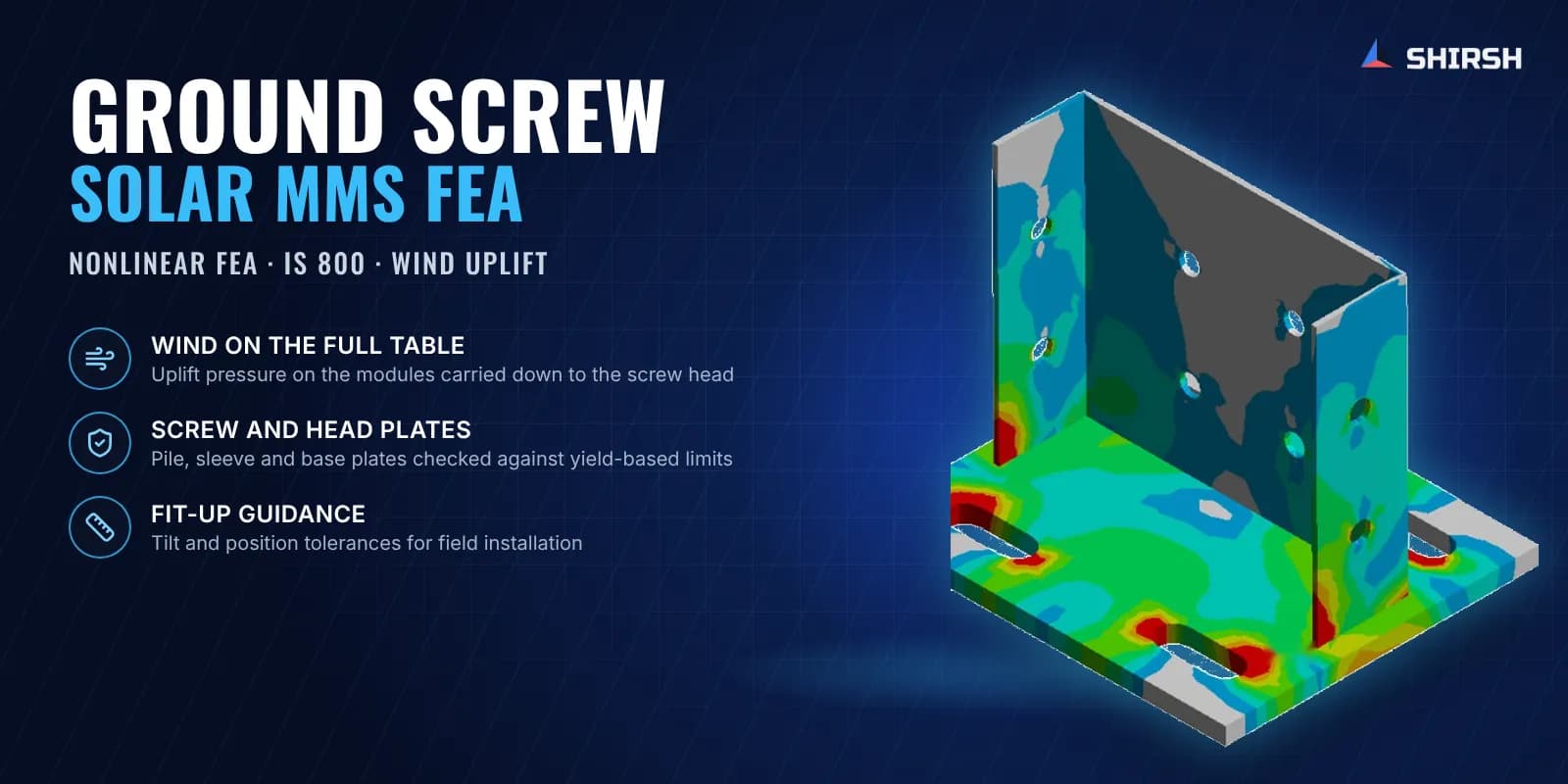
Ground screw under the support reactions. We built a solid model of the ground screw from the client's CAD, with its sleeve, head plate and helical tip. The embedded length was restrained, and the force and moment reactions from the client's structure design were applied at the head as remote loads.
The load combinations of dead load with wind load from the reaction table were screened and the governing case was analysed.
Von Mises stress in the screw upper part and sleeve was compared with an allowable based on yield strength and a factor of safety.
Where the plates and the sleeve were working hard, revised thicknesses were proposed.
Full fixed-tilt table on ground screws. The complete mounting structure was then modelled with its cold-formed column, rafters, front and rear bracing and hat purlins, the modules in portrait on the purlins, and the ground screws with their channel and square base plates.
Static structural, nonlinear analysis with self weight and wind pressure applied normal to the module faces.
Variable pressure distribution across the table so the uplift is heavier where it really acts.
Deformation of the whole table and of the head plates, and stress in the channel plate, square plate and the screw.
Installation guidance. Alongside the FEA we issued a short recommendation note covering tilt and position tolerances, adjustable connections such as slotted base plates and telescopic columns, torque-controlled driving, deeper embedment and dual screws for weak ground.
Common questions
Why use FEA for a ground screw foundation when the pile capacity is already known? Pull-out and lateral capacity tell you whether the soil holds the screw. They say nothing about the welded sleeve and plates at the head, which carry the full uplift and moment from the solar table. FEA shows where these plates are stressed and how thick they need to be.
How should tilt and positional errors in ground screws be handled on a solar plant? Set a clear tolerance for tilt and position before work starts, use slotted base plates or adjustable brackets to absorb small errors, and re-drive a screw that falls outside the band. Torque-controlled installation and pilot templates keep most screws inside it in the first place.
Challenges we overcame
A welded sleeve and plate detail with no design-by-rule method to size it
Uplift and moment from the whole module table concentrated at one small connection
Two separate checks to link: the screw under reaction loads and the full table under wind pressure
Cold-formed members of different steel grades in one model
Field tilt and position errors that the structure had to tolerate
Clear, buildable design changes needed quickly for a product going to site
How we executed
- 1
Reviewed the client's ground screw CAD and the support reaction table from their structure design
- 2
Built the ground screw model with the embedded length restrained and applied the governing head reactions
- 3
Checked screw and sleeve stresses against the yield-based allowable and proposed revised plate and sleeve thicknesses
- 4
Issued a note on tilt and position tolerances and installation practice for ground screw foundations
- 5
Modelled the complete fixed-tilt table with columns, rafters, bracing, purlins, modules and ground screws
- 6
Applied self weight and variable wind pressure on the module faces with the load combination per IS 800
- 7
Reviewed deformation of the table and stress in the channel plate, square plate and screw
- 8
Reported the final design changes to the head plates in a detailed report
Project outcome
The ground screw body stayed within the allowable stress limit of its material in the governing load case.
The FEA located the stress at the slots and welds of the head plates and gave the client specific, thicker plate and sleeve sizes to adopt.
On the full table under wind uplift, deformations stayed small and the channel and square base plates were confirmed as the parts to strengthen, with a thicker plate size recommended for both.
The client received practical tolerance and installation guidance for tilt and positional shift on site.
Project gallery
Where this lives
At a glance
We apply the same rigour to every engagement
Let us show you what's possible for your product.