
Wind Load FEA of a Telescopic Communications Mast to IS 875 Part 3
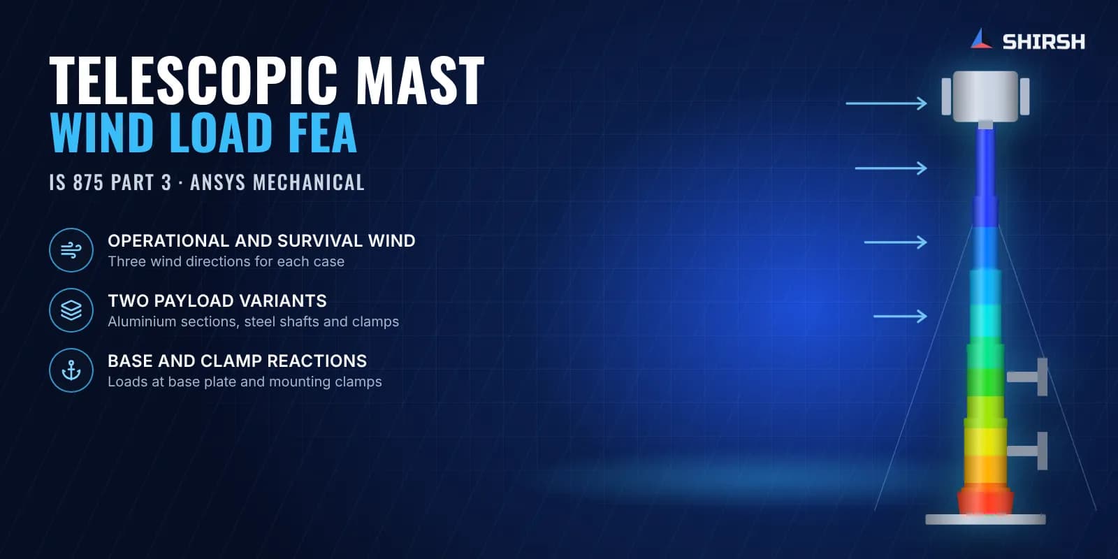
Static FEA of a telescopic communications mast in two payload variants, under operational and survival wind from three directions to IS 875 Part 3.
Project brief
A manufacturer of telescopic masts for communication equipment needed structural sign-off on a mast offered in two payload variants. Its customers wanted evidence that the mast, the head load on top and the fixings at the base would stay safe in high wind.
Shirsh Technosolutions converted the wind loads to IS 875 Part 3 and analysed both variants in ANSYS Mechanical. Besides stress and deflection, the client asked for the reaction forces at the base plate and mounting clamps, since those feed straight into the design of the vehicle or structure the mast is fixed to.
What was at risk
The mast is a nest of aluminium alloy tubes with collars, pistons and stoppers, raised by steel ropes over pulleys and held at the bottom by a base cup, base plate and steel mounting clamps. One assembly mixes aluminium alloy, stainless steel, phosphor bronze guide keys and mild steel, with bolted and welded joints throughout.
Wind acts on the head load and along the tubes. It had to be checked at an operational and a survival wind speed, each from three directions: parallel to the mounting bracket, perpendicular to it and diagonally across. The bottom shafts, collars and clamps carry the full overturning moment, so they were the parts most likely to govern.
Solution offered
Wind speeds were converted to design pressures, and then to forces on the head load and tube sections, following IS 875 Part 3. These were applied to a full model of each mast variant.
The long tube sections were meshed with shell elements, and the collars, shafts, clamps and plates with quadratic hexahedral and tetrahedral solids. Bolted joints were represented with beam elements and frictionless contacts, welded joints with bonded contacts, and the steel ropes with spring elements so they carry tension the way the real cabling does.
Each variant was solved for both wind levels in all three directions. For every case we reported equivalent stress in each part, mast deflection, reaction forces at the base plate and clamp screws, rope end forces and bolted joint stresses. When the client asked for a closer look at the bottom shafts we issued dedicated plots for every load case, and the final reports went out in editable form so the client could add its own general arrangement drawing.
Common questions
How is a wind speed turned into a load for FEA? IS 875 Part 3 gives the design wind speed and pressure from the basic wind speed, with factors for terrain, height and risk. Pressure times the exposed area, with a force coefficient for the shape, gives the force applied in the model.
Why report base and clamp reactions? A mast is only as safe as what it is bolted to. The reactions let the vehicle or tower designer check their own structure and fixings.
Challenges we overcame
Converting operational and survival wind speeds into forces to IS 875 Part 3
Two payload variants, each run at two wind levels in three directions
Mixed materials: aluminium alloy tubes, stainless and bronze parts, steel clamps
Bolted joints, welded joints and tensioned steel ropes in one model
Bottom shafts and clamps carrying the full overturning moment
How we executed
- 1
Reviewed the STEP assemblies and material lists for both variants
- 2
Converted wind speeds to pressures and forces on the head load and tubes to IS 875 Part 3
- 3
Meshed the tubes with shells and the shafts, collars, clamps and plates with quadratic solids
- 4
Modelled bolts with beams and frictionless contacts, welds with bonded contacts and ropes with springs
- 5
Solved operational and survival wind in three directions for each variant
- 6
Reported part stresses, mast deflection, rope forces and bolted joint stresses
- 7
Extracted reaction forces at the base plate and mounting clamp screws for every case
- 8
Issued bottom shaft plots on request and the final reports in editable form
Project outcome
Stresses in the mast parts stayed within the allowable limits in the load cases checked.
Mast deflection was reported for every case, so the client could judge the effect on the payload.
Base plate and clamp reactions gave the client the loads for its mounting design.
Both payload variants were covered with one consistent method and report format.
Project gallery
Where this lives
Software used
Related solutions
Industries
At a glance
We apply the same rigour to every engagement
Let us show you what's possible for your product.