
Rolling Shutter Wind Load FEA to IS 875 Part 3 and ASCE 7-10
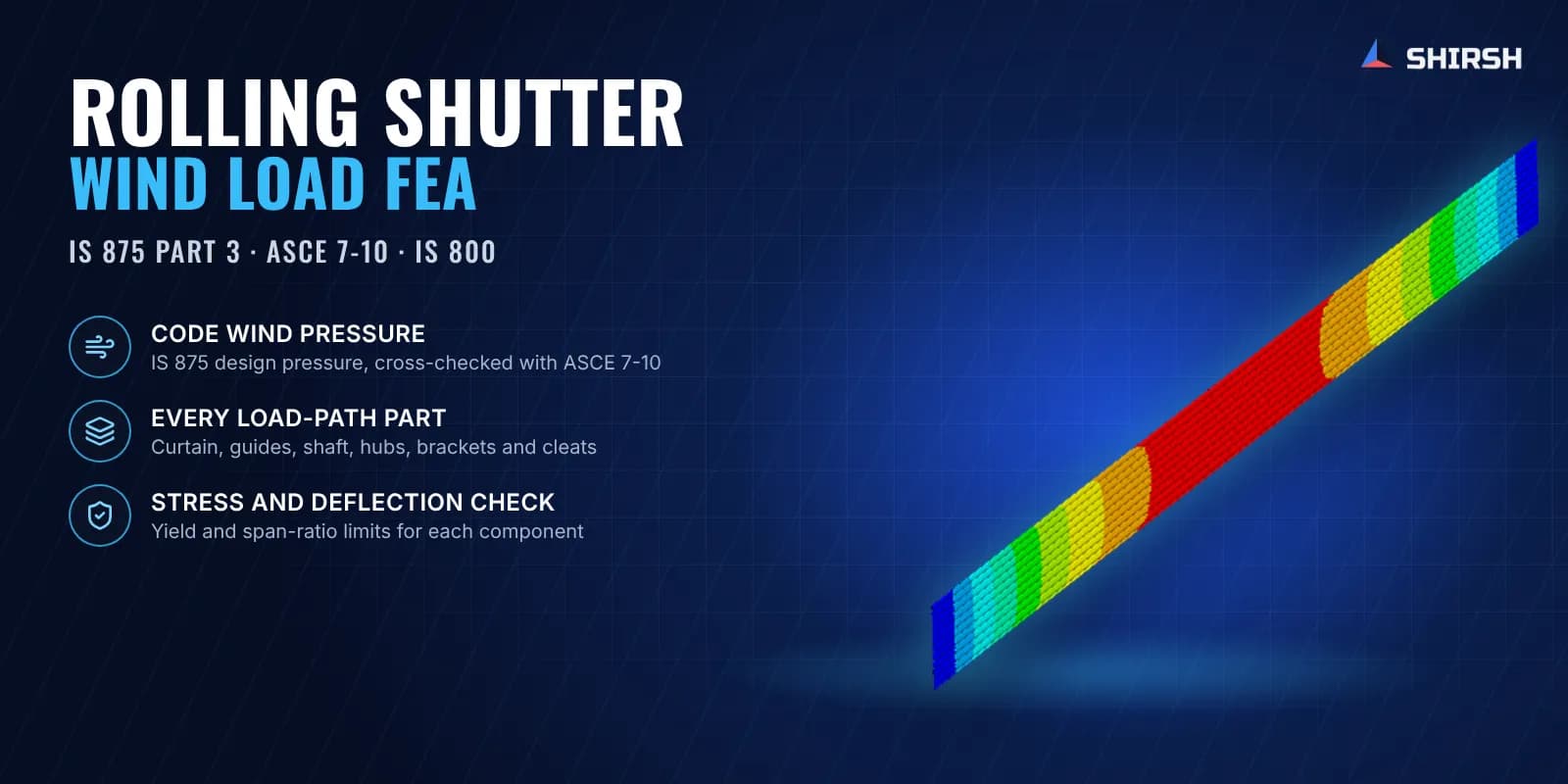
Wind load FEA of a large industrial rolling shutter to IS 875 Part 3 and ASCE 7-10, with curtain, guides, shaft, hubs and brackets checked.
Project brief
An industrial door and shutter manufacturer needed a structural stability report for its large rolling shutters before they went to site. Buyers and consultants wanted evidence that the curtain, the guides and the drive end would carry the design wind pressure without overstressing or bowing out of the guides.
Shirsh Technosolutions worked out the design wind pressure to IS 875 Part 3, cross-checked it with ASCE 7-10, and ran a finite element analysis in ANSYS of every part in the load path. Each component got a clear stress and deflection check, and the manufacturer received a report it could hand to its customers with the code clauses spelled out.
What was at risk
A big rolling shutter behaves like a tall, flexible wall that is only held at its two edges and at the top. Wind on the curtain pushes the interlocked strips outward, the strips pull on the side guides, and the shaft at the top carries the rest through its hubs into the end brackets. If any one of those parts is undersized, the curtain can pop out of the guides or the drive end can bend.
The manufacturer had a family of shutter sizes and needed each one checked in the same, traceable way:
what design wind pressure the shutter should be designed for, and which code governs
whether the curtain strips and their interlocks stay within the allowable stress
whether the side guides with wind locks can take the pull from the curtain
whether the shaft, hubs, brackets and cleats at the drive end are strong and stiff enough
whether curtain and shaft deflections stay within the span limit
The report also had to be clear enough for the client's sales and technical teams to answer customer questions clause by clause.
Solution offered
Design wind pressure from the codes. We built up the design pressure to IS 875 Part 3, using the basic wind speed for the zone, the terrain and topography factors, and internal and external pressure coefficients for a building of medium permeability. The same shutter was then checked to ASCE 7-10 for an enclosed building, and the higher of the two pressures was carried into the analysis.
Wind zone, terrain category and risk factor taken from IS 875 Part 3.
Internal pressure coefficient chosen for medium permeability, external coefficient from the code tables for the wall.
ASCE 7-10 pressure worked out as a cross-check, so the design is not tied to a single code.
A finite element model of the whole load path. The curtain, interlocks, side guides with wind locks, shaft, hubs, motor-side and brake-side brackets and cleats were modelled in ANSYS. Thin parts were meshed with shell elements and the hubs and brackets with higher-order solid elements, with bonded connections standing in for the welds. Structural steel to IS 2062 was used throughout.
Component-by-component checks. For each part we reported von Mises stress, shear stress and deflection under the design pressure. Stresses were checked against the yield strength of the steel, and curtain and shaft deflections against the span/180 limit from IS 800. The summary table gave the manufacturer one line per component, which made it easy to see which parts had margin and which were working hardest.
Common questions
Which code should be used for wind load on a rolling shutter in India? IS 875 Part 3 is the base code for wind pressure on buildings and their openings in India. Checking the same shutter against ASCE 7-10 is useful when a project or buyer follows US practice, and designing for the higher of the two pressures keeps the shutter safe under either.
Why run FEA on a rolling shutter when hand calculations exist? Hand formulas treat the curtain and shaft as simple beams. FEA follows the real load path from curtain to guides, shaft, hubs and brackets, and shows where stress concentrates at steps, welds and bolt holes, which is where large shutters tend to give trouble.
Challenges we overcame
A large, flexible curtain held only at its edges and top
Wind pressure that had to satisfy both Indian and US codes
Load passing through several parts, each with its own failure mode
Stress concentration at shaft steps, hubs and bracket welds
Deflection limits on the curtain and shaft as well as strength
A report that customers and consultants could follow clause by clause
How we executed
- 1
Collected the shutter general arrangement drawing, strip profile and material data from the client
- 2
Calculated the design wind pressure to IS 875 Part 3 for the given wind zone and permeability
- 3
Cross-checked the pressure to ASCE 7-10 and carried the governing value forward
- 4
Built a finite element model of the curtain, guides, shaft, hubs, brackets and cleats in ANSYS
- 5
Applied the design pressure to the curtain and transferred the reactions through the load path
- 6
Extracted von Mises stress, shear stress and deflection for every component
- 7
Checked stresses against the steel yield strength and deflections against the span/180 limit of IS 800
- 8
Issued a structural stability report with code clauses, plots and a component summary table
Project outcome
The governing design pressure came from IS 875 Part 3, which was higher than the ASCE 7-10 value, so the shutter was designed for the more demanding of the two.
Every component in the load path, from curtain to cleats, stayed within the yield strength of the steel under the design wind pressure.
Curtain and shaft deflections stayed within the span/180 limit.
The manufacturer received a structural stability report with the code clauses written out, ready to share with its customers.
Project gallery
Where this lives
Software used
Related solutions
Industries
At a glance
We apply the same rigour to every engagement
Let us show you what's possible for your product.