Single-Axis Solar Tracker CFD and FEA: Wind Pressure Mapping and Structural Qualification
Single-axis solar tracker CFD and FEA: wind pressures at three tilt positions mapped onto a nonlinear ANSYS model, plus an IS 800 pivot bolt check.
Project brief
A single-axis solar tracker spends its life turning, so the wind it has to resist changes with every tilt position. Shirsh Technosolutions carried out the CFD and FEA for a solar EPC company that was developing its own rope-driven single-axis tracker for ground-mount plants. The job was to find the real wind pressure on the modules at the tilt positions that matter, carry those pressures straight into a structural model of the full tracker table, and show that each part of the structure works within its allowable limits.
The CFD and the structural model were built in ANSYS. Every member and joint was checked against yield-based allowables and deflection limits, and the pivot bolt between the rafter and the column post was checked to IS 800. The final reports covered two purlin options, a hat section and a C-channel, so the client could choose either with confidence.
What was at risk
Codes give wind pressure coefficients for fixed, flat-plate structures, but a tracker is a moving plate on a slender post. At a flat position the wind runs along the modules. At a steep tilt the table acts more like a sail, and wind from the back of the modules sucks the surface instead of pushing it. The client needed loads that reflect this, and it needed them for its own geometry, which mixes cold-formed purlins and posts with a curved drive rack, a pivot arm and a set of welded plates and cleats.
The first structural run on the client's prototype geometry showed stresses above the allowable limits in some members, so the section sizes were not yet settled. The design also kept moving: the rafter and column post assembly was revised, and the client later asked for a C-channel purlin in place of the hat section. Each version had to be reassessed on the same basis, quickly enough to support an internal design review.
Solution offered
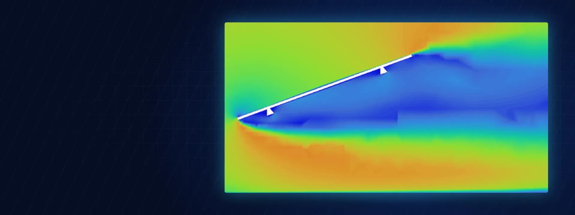
Wind pressures by CFD. We built an air domain around the tracker table and solved incompressible, turbulent flow with the k-omega SST model. An atmospheric wind profile following the one-seventh power law was applied at the inlet, with a pressure outlet and symmetry on the side and top walls. The mesh was poly-hexcore with inflation layers on the module and structure surfaces to capture the boundary layer.
Three tilt positions: flat, an intermediate tracking angle and a high tilt, each with the wind speed that applies at that position.
Side wind, upwind and downwind directions for the tilted cases, giving eight load cases in all.
Pressure distribution on the top and bottom faces of the modules, plus velocity and pressure fields through the table.
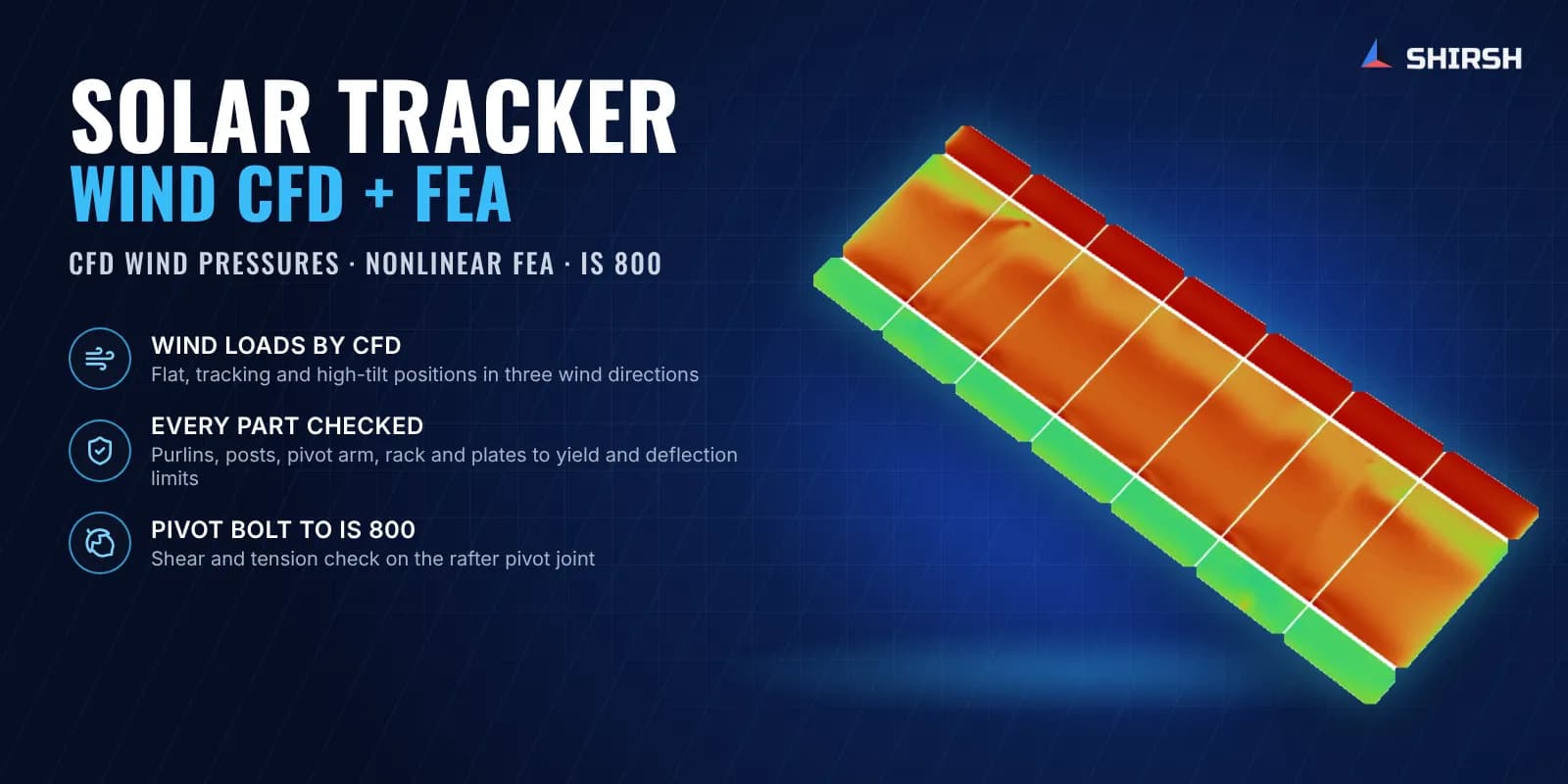
Structural FEA with mapped pressures. The CFD surface pressures were imported directly into a static structural model in ANSYS Mechanical, so the FEA sees the true, uneven pressure on each module and not an averaged code value. The model used solid and shell elements with nonlinear analysis, the column post bases were fixed, and self weight was included in every case.
Von Mises stress in the purlins, column posts, pivot arm, curved rack, pulley fin, rafter support plate, eye-bolt plate and L-angles, each compared with an allowable based on its yield strength.
Deflection of purlins (simply supported and cantilever spans), rafters and column posts against span and height limits.
Shear and tension in the shoulder bolt at the rafter pivot, checked by hand to IS 800 using the forces from the FE model.
The same model was rerun with a C-channel purlin so both options could be reported side by side.
Common questions
Why use CFD wind loads for a solar tracker instead of code pressure coefficients? Code coefficients are written for fixed panels and give an average pressure. A tracker changes tilt, and the pressure on its modules is uneven, with high suction on the back face in some wind directions. CFD gives the actual pressure map at each tilt, and mapping it into the FEA puts the load where it really acts.
Which load case usually governs a single-axis tracker? It depends on the geometry. In this study the upwind case at the intermediate tracking angle governed, because the wind lifts the modules from behind and loads the pivot and the drive rack together. That is why each tilt and wind direction needs its own check, and the flat or stow position alone is not enough.
Challenges we overcame
Wind pressure on a moving table that changes with every tilt position
Suction on the back face of the modules in upwind cases, which codes do not show clearly
Carrying an uneven CFD pressure map into the structural model without simplifying it
Many small welded plates, cleats and a curved drive rack, each needing its own check
A design that changed during the job, including a switch of purlin section
Prototype sections that did not pass at first and had to be revised
How we executed
- 1
Reviewed the client's tracker CAD, module data and the tilt positions and wind speeds to be covered
- 2
Ran an early FEA on the prototype geometry and revised the column and rafter sections where stresses were too high
- 3
Built the CFD domain and poly-hexcore mesh and solved eight tilt and wind-direction cases
- 4
Extracted surface pressures on the top and bottom faces of the modules
- 5
Mapped the pressures into a nonlinear static structural model of the full tracker table
- 6
Checked stresses and deflections for every structural part in every load case
- 7
Checked the rafter pivot shoulder bolt for shear and tension to IS 800
- 8
Repeated the analysis with a C-channel purlin and issued reports for both options
Project outcome
All members, plates and bolts stayed within their allowable stress limits in every load case, for both the hat and the C-channel purlin options.
Purlin, rafter and column post deflections were within the span and height limits in all cases.
The pivot shoulder bolt passed the IS 800 shear and tension checks with a good margin.
The CFD showed the downwind cases loading the top face of the modules and the upwind cases loading the bottom face, which pointed to the upwind tracking position as the one that governs the structure.
The client had a qualified structure in both purlin options to take into its internal design approval.
Project gallery
Where this lives
Related insights
Why Single-Axis Solar Trackers Need FEA, CFD and Aeroelastic Analysis Beyond IS 875
A single-axis solar tracker can clear every line of IS 875, pass its static frame analysis, and still fail in a windstorm that never reached the code design speed. The reason is uncomfortable but simple: the code hands you a static pressure, and the structure that tore apart was responding to a dynamic, fluid-structure problem the code was never written to see. This is sharpest with single-axis trackers, which behave less like a stiff steel frame and more like a bridge deck on a torsional spring. Here is where IS 875 stops, where FEA and CFD pick up, and why "passes the code" and "survives the wind" are two different questions.
ReadWhy Fixed-Tilt Ground-Mount Solar Structures Fail
Fixed-tilt ground-mount is the structure everyone treats as solved. No moving parts, a straight load path from module to rail to post to ground, a static wind check, done. That reputation for simplicity is precisely why these structures fail, not from exotic physics, but from foundations pulled out of the soil, connections detailed for the wrong load direction, slender members that buckled under uplift, and corners that saw far more wind than a borrowed coefficient ever admitted. Walk the load path with a failed array in front of you and the causes are rarely mysterious. Here is how to read the damage, and the analysis chain that would have caught it on paper.
ReadHow to Check a Cold-Formed Solar Mounting Structure to IS 801: A Step-by-Step Guide
Most ground-mounted solar structures in India are made from cold-formed steel: thin steel sheet bent into channels and hat sections. Engineers find the wind load from IS 875 Part 3, then check the steel using IS 801. Two mistakes are very common. First, engineers use the full cross-section, but thin steel does not work that way: part of it buckles early, so the code makes you use only the "effective" part. Second, engineers check only the steady (static) load and skip the moving (dynamic) effects. This guide explains both problems in simple steps. It then checks the four main members of a solar structure: post, rafter, bracing, and a 1 mm hat purlin: with full numbers, so you can see exactly where the common shortcuts go wrong.
ReadFour Quiet Ways the IS 875 Wind Load Goes Wrong on a Solar Array
The wind-load calculation almost never fails an audit. It fails the structure. IS 875 (Part 3) is a sound loading code, and the arithmetic in most reports is right. What moves the answer is a handful of small choices in how the code gets applied, and on a light tilted array those small moves decide which members are under-built. Here is the chain done properly, and the four places it usually slips.
ReadAt a glance
We apply the same rigour to every engagement
Let us show you what's possible for your product.