PV Module Frame FEA Under Wind and Snow Load: Choosing the Right Aluminium Profile
PV module frame FEA under wind and heavy snow load: three aluminium extrusion profiles compared with a full laminate model and a Coulomb-Mohr check.
Project brief
A solar module manufacturer wanted to know which aluminium frame extrusion could carry its modules through high wind and heavy snow before committing to tooling and certification testing. Three candidate profiles were on the table: two of the manufacturer's own sections and one frame already in use by another module maker.
Shirsh Technosolutions modelled each framed module as a full laminate on its mounting points and ran a nonlinear finite element analysis for wind and snow pressure. Every frame got a clear pass or fail against a fracture-based criterion, so the client could drop the weak options on paper instead of finding out on the test rig.
What was at risk
A PV module frame is a thin aluminium extrusion, yet it does a lot of work. It holds the glass laminate, takes the pressure from wind and snow, and passes it to the mounting rails through a few bolt points. Make the section lighter and the module gets cheaper, but the long sides start to bow and the stress near the supports climbs quickly.
The client's questions were simple to ask and harder to answer:
which of the three profiles would survive the wind load and the heavy snow load
how far the long sides of each frame would deflect, since the glass laminate rides on them
whether a lighter wall section could still be used
There was a practical difficulty too. Datasheets for the encapsulant and backsheet give tensile strength and thickness, but not the stiffness an FE model needs, so suitable values had to be agreed with the client before the analysis could start.
Solution offered
Full laminate model on its real supports. We built each module as it sits on site: the aluminium frame with its corner joints, the glass, the front and back encapsulant layers, the silicon cells and the backsheet, carried on purlins at the bolting points. Quarter symmetry kept the model efficient without losing the behaviour along the long and short sides.
Layer thicknesses taken from the client's laminate build-up and datasheets.
Glass, cell and aluminium properties from published material data, and encapsulant and backsheet stiffness agreed with the client's module engineering team.
Aluminium 6063 frame modelled with an elastic-plastic stress-strain curve, so local yielding near the supports is captured instead of being hidden by a linear model.
Frame fixed at the bolt locations on the purlins, following the module mounting instructions.
Two load cases per frame. A uniform wind pressure and a heavy snow pressure were applied normal to the module face, at the static mechanical load levels commonly used for module qualification. Each frame was run for both, with deflection and principal stresses extracted along the full perimeter.
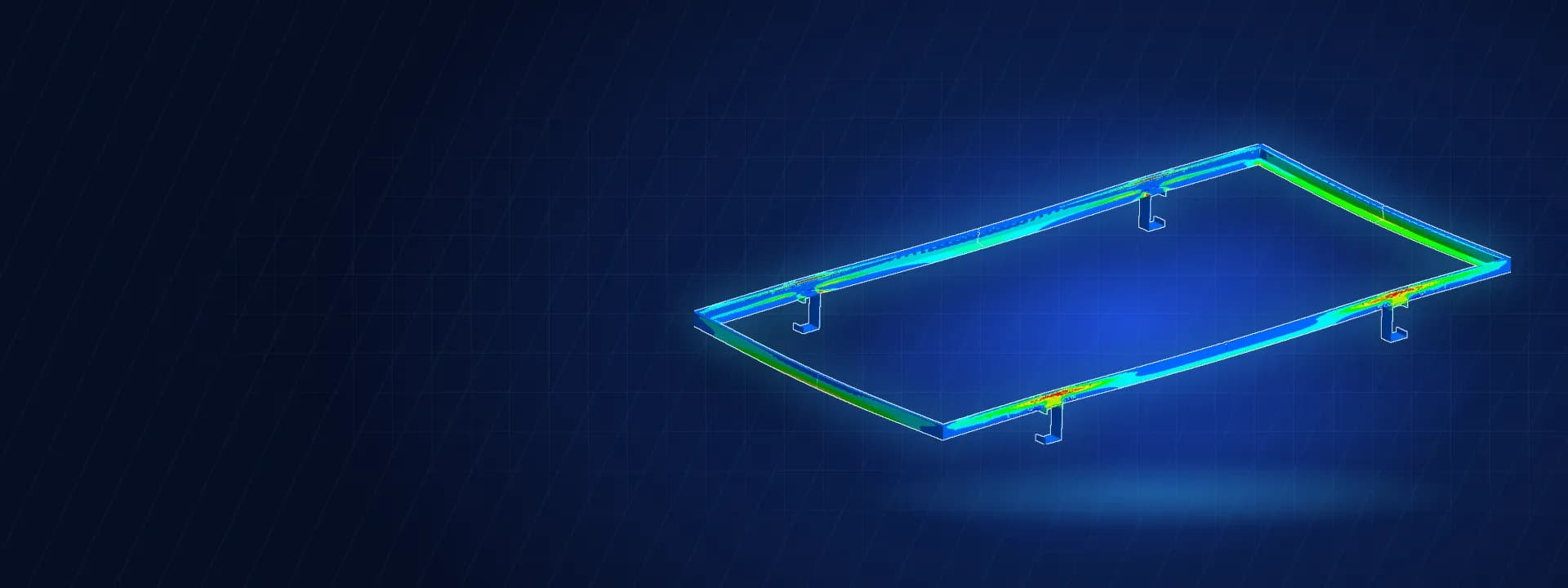
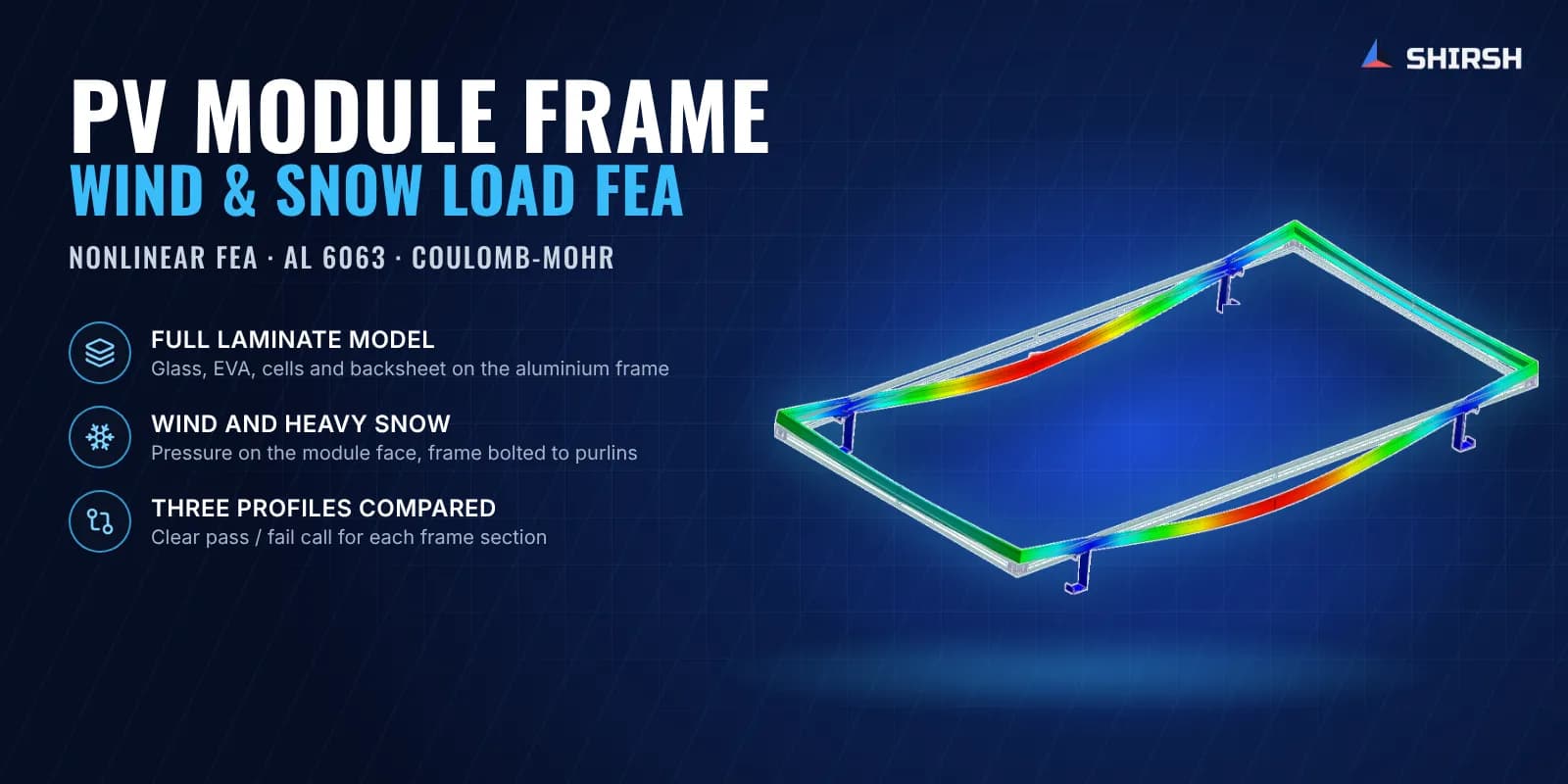
A fracture-based pass/fail check. The frame was judged with the Coulomb-Mohr criterion, which combines the maximum and minimum principal stresses against the ultimate tensile and compressive strength of the alloy. A failure plot for each load case showed exactly where on the frame the limit was reached, which is more useful to an extrusion designer than a single peak stress.
Common questions
Why model the whole laminate and not just the aluminium frame? The glass laminate stiffens the frame and shares the load. A frame-only model misses that, and it also misses how the pressure on the glass reaches the frame edges, so its deflections and stresses do not reflect the module as built.
Can FEA replace the mechanical load test for a PV module? No. Certification still needs the physical test. FEA is the cheaper first filter: it shows which frame profiles are likely to pass, where they will fail and why, before extrusion dies are cut and test modules are built.
Challenges we overcame
Thin aluminium extrusions where small changes in section decide pass or fail
A multi-layer glass laminate with very different stiffness in each layer
Missing stiffness data for the encapsulant and backsheet in supplier datasheets
Local yielding near the bolt supports that a linear model would not show
Three competing frame profiles compared on exactly the same basis
A clear design call needed before tooling and certification testing
How we executed
- 1
Collected the frame extrusion drawings, laminate build-up and material datasheets from the client
- 2
Agreed the material properties for each laminate layer with the client's module engineering team
- 3
Built a quarter-symmetric solid model of the framed module on its purlin supports for each profile
- 4
Assigned an elastic-plastic curve to the aluminium 6063 frame and elastic properties to the laminate layers
- 5
Applied the wind and heavy snow pressure normal to the module face with the frame fixed at the bolt points
- 6
Ran nonlinear static analysis and extracted deflection and principal stresses for every frame
- 7
Checked each frame with the Coulomb-Mohr criterion and mapped the critical zones
- 8
Reported a pass or fail for each profile and load case, with plots, to the client's module and structural teams
Project outcome
All three frame profiles stayed within the Coulomb-Mohr limit under the wind load.
Under heavy snow, only the stiffer of the client's sections stayed within the limit, and it was found safe for both wind and snow.
The two lighter profiles, including the frame already used by another module maker, went past the limit under snow, with the critical zone along the long sides between the supports and much larger deflection.
The client got a pass or fail for every profile and load case, with failure plots showing where each frame would give way, before any further tooling or testing.
Project gallery
Where this lives
At a glance
We apply the same rigour to every engagement
Let us show you what's possible for your product.