
Ventilation, Cleanroom and Fume Control CFD
CFD of airflow, contaminant removal and containment for basements, cleanrooms, laboratories and fume hoods, used to fix the layout before it is built.
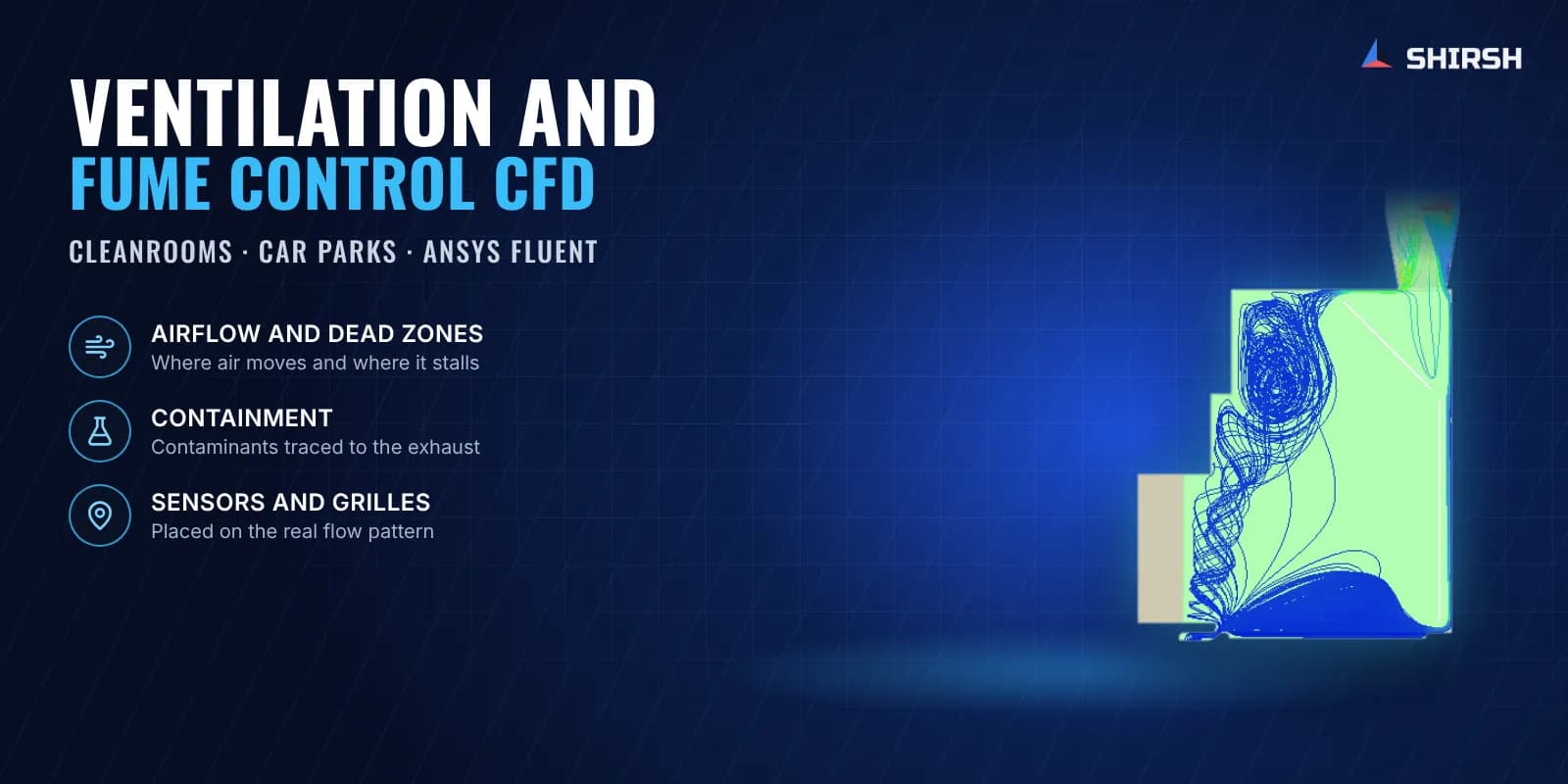
What this solution covers
Whether a space stays safe and clean depends on how the air actually moves through it, and air-change calculations cannot show that. Shirsh Technosolutions models the airflow in ANSYS Fluent for car parks and basements, pharmaceutical cleanrooms, laboratories and fume hoods.
The model shows where supply air goes, where it stalls and where contaminants collect. Designers can then move diffusers, exhaust points, sensors or baffles on screen and check the result before any ductwork goes in.
Pain points we address
Stagnant zones where exhaust gases or contaminants build up
Cleanroom airflow not holding at critical points around equipment and operators
Fume hoods and enclosures that may spill back towards the user
CO and gas sensors placed by guesswork
Costly rework after installation when the airflow falls short
What we solve
Airflow and contaminant dispersion in enclosed car parks and basements
Cleanroom and laminar airflow patterns around equipment and operators
Fume hood and enclosure containment, and the flow split between openings
Placement of sensors, diffusers, exhaust grilles and jet fans
Comparison of alternative layouts before construction
How we approach it
- 1
Build the space from drawings, with obstructions, openings, equipment and sources
- 2
Mesh with poly-hexcore cells and wall prism layers, refined near inlets and outlets
- 3
Solve steady RANS with a suitable turbulence model, adding species transport for contaminants
- 4
Set supply, exhaust and openings to match the design or measured airflow
- 5
Review velocity, streamlines and concentration at occupant and work heights
- 6
Test layout changes and report the arrangement that meets the requirement
Deliverables
CFD report with velocity, streamline and concentration plots
Flow balance across supply, exhaust and openings
Recommended layout changes and sensor locations
Comparison of design options
Expected outcomes
Dead zones and short-circuiting found at the design stage
Sensor and grille positions based on the actual flow pattern
Evidence to support design approval and validation documents
Less rework at site after commissioning
Why Shirsh
We combine CFD with a working knowledge of how HVAC systems are designed and commissioned. Our models include the obstructions, openings and sources that really drive the flow, and our reports turn the results into layout changes an HVAC contractor can act on.
Where this lives
Software used
Related case studies
CFD Airflow Study of a Bench-Top Laboratory Fume Hood
Steady RANS CFD of a bench-top fume hood at two sash positions, used to understand how it captures fumes and to check a revised liner design.
ReadCFD of Ventilation and Exhaust Gas Dispersion in a Basement Car Park
CFD of airflow and exhaust gas dispersion in an enclosed basement car park, used to check the ventilation layout and place CO sensors.
ReadRelated insights
Electrolyser Halls: What Air Changes Can and Cannot Do for Hydrogen
A room-average check can show a small hydrogen leak diluted to a few percent of the LFL, while a larger hole in the range IEC 60079-10-1 works with fills the same room past the LFL in under four minutes. We set out what the 2020 edition asks for and run the check on a generic electrolyser room.
ReadBESS Container HVAC: Why One Rack Runs Hot and What CFD Shows
A BESS container HVAC unit controls on its return air, and that reading can stay the same while the racks inside breathe very different air. We ran four OpenFOAM cases on a generic ten-rack container to show which rack ran hottest, why 30% more airflow barely changed the pattern, and how swapping the supply and return closed most of the gap.
ReadCar Park Ventilation: Why CO Sensors Miss the Moving Dead Zones
A car park can meet its air change rate and still have corners where exhaust gas lingers, because the rate says nothing about the route the air takes. We ran four OpenFOAM cases on a generic basement to show where the dead zones sit with extract fans alone, what four jet fans change, how one fan out of service moves the problem, and what six ordinary aisle sensors actually see.
ReadBESS Container Gas Venting: What CFD Adds to NFPA 69 Ventilation
A dilution ratio says a ventilated BESS container stays at 10 percent of the lower flammable limit. A small OpenFOAM study of a 20 ft container shows hydrogen layering under the roof, a fifth of the air above the NFPA 69 limit in the usual fan layout, and how moving the same fan changes the picture.
ReadGrade A Under a LAF: Where Smoke Studies and CFD Each Fool You
An air speed check at the working position can look better with a hopper over the vials than with the table empty, while the vials get no first air at all. A small OpenFOAM study of a Grade A zone under a laminar airflow unit shows how a hopper or an operator's arm turns the flow over the critical zone, and what a smoke study and a CFD model can each tell you.
ReadNFPA 855 (2026): Why Deflagration Venting Alone No Longer Covers BESS
The 2026 edition of NFPA 855 no longer lets deflagration vent panels carry a BESS explosion control design on their own. We summarise what the published reviews say changed and run a quick check on a 20 ft container to show why the average gas concentration is not the whole story.
ReadAnnex 1 Clean-Up Period: Where a 20-Minute Pass Can Mislead
EU GMP Annex 1 sets a clean-up guidance of less than 20 minutes, but the result only holds where it is measured. A two-zone check on a generic Grade B room shows the main zone clearing in under 10 minutes while a poorly swept pocket takes 30.
ReadWant to learn this?
We also offer ANSYS & SolidWorks training courses.
At a glance
Discuss your project with our engineers
Tell us about your simulation, validation or design challenge.