
CFD Airflow Study of a Bench-Top Laboratory Fume Hood
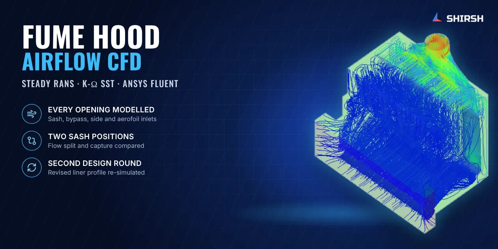
Steady RANS CFD of a bench-top fume hood at two sash positions, used to understand how it captures fumes and to check a revised liner design.
Project brief
A laboratory equipment manufacturer wanted to understand how air moves through its bench-top fume hood. A fume hood protects the user only if air flows steadily inwards at every opening and carries contaminants to the exhaust without spilling back into the room.
Shirsh Technosolutions ran CFD of the hood in ANSYS Fluent over two design rounds. The first round mapped the flow in the original design. The client then revised the liner profile using those findings, and the second round checked the revised hood under the same conditions so the two designs could be compared directly.
What was at risk
Air enters the hood through several paths at once: the main sash opening, a bypass opening, small openings at each side and the aerofoil slot along the front edge of the work surface. All of it leaves through a single exhaust collar. How the flow divides between these paths, and how the streams meet inside the chamber, decides whether fumes are swept away or left circulating near the user.
In daily use the hood also runs at different sash heights, so the flow had to be understood at both a low and a high sash position.
Solution offered
We extracted the internal air volume from the client's CAD for each sash position and meshed it with a poly-hexcore mesh, with prism layers along the walls to resolve the boundary layer. Mesh quality was checked before solving.
The flow was solved as steady, incompressible and turbulent using the RANS equations with the k-ω SST turbulence model. The exhaust was set as a mass flow outlet at the design extraction rate and every opening was left at atmospheric pressure, so the hood itself decided how much air each path drew, as a real hood does on its exhaust fan.
Results were reviewed as streamlines traced from each opening on its own, velocity contours and vectors on section planes, pressure contours and a mass flow balance across all boundaries. Tracing each inlet separately showed exactly where its air travelled before reaching the exhaust.
Common questions
Why leave the openings at atmospheric pressure instead of fixing inlet velocities? Fixed velocities force the answer. With the exhaust flow set and the openings free, the split between sash, bypass and aerofoil comes out of the geometry, which is the thing being designed.
Can CFD replace a containment test? CFD explains the flow and lets designs be compared quickly and cheaply. Formal containment testing to the applicable standard is still done on the physical hood.
Challenges we overcame
Several inlet paths sharing one exhaust, with the flow split not known in advance
Two sash positions to cover normal use
Recirculation behind the glass and below the exhaust where the bypass and sash streams meet
Mixing at the aerofoil corners close to the work surface
Comparing the original and revised liner on equal terms
How we executed
- 1
Extracted the air volume from the CAD for each sash position
- 2
Meshed with poly-hexcore cells and wall prism layers, and checked mesh quality
- 3
Set the exhaust as a mass flow outlet and all openings at atmospheric pressure
- 4
Solved steady RANS with the k-ω SST turbulence model
- 5
Traced streamlines from each opening and plotted velocity and pressure on section planes
- 6
Checked the mass flow balance and flow split across every boundary
- 7
Shared the findings with the client for the liner revision
- 8
Re-ran the revised liner at both sash positions with the same set-up
Project outcome
At both sash positions most of the incoming air enters through the sash, with the bypass, side and aerofoil openings drawing a small share.
The bypass and sash streams meet behind the glass and below the exhaust, setting up a recirculation that mixes and dilutes the air before it leaves.
Air from the aerofoil slot is swept up by the sash flow at the chamber corners, which keeps air moving across the work surface.
The first round gave the client a flow-based reason for revising the liner, and the second round documented the revised design.
Both designs were analysed with an identical set-up, so the comparison is like for like.
Project gallery
Where this lives
Software used
Related insights
BESS Container Gas Venting: What CFD Adds to NFPA 69 Ventilation
A dilution ratio says a ventilated BESS container stays at 10 percent of the lower flammable limit. A small OpenFOAM study of a 20 ft container shows hydrogen layering under the roof, a fifth of the air above the NFPA 69 limit in the usual fan layout, and how moving the same fan changes the picture.
ReadHot-Aisle Containment: What CFD Shows That Rack Inlet Sensors Miss
A rack inlet sensor at mid-height can read 20 °C on every rack while 28.7 percent of the inlet area is above the 27 °C recommended limit. A small OpenFOAM study of one rack row, with and without hot-aisle containment, shows where the hot air gets in and why containment only helps once the airflow matches the racks.
ReadGrade A Under a LAF: Where Smoke Studies and CFD Each Fool You
An air speed check at the working position can look better with a hopper over the vials than with the table empty, while the vials get no first air at all. A small OpenFOAM study of a Grade A zone under a laminar airflow unit shows how a hopper or an operator's arm turns the flow over the critical zone, and what a smoke study and a CFD model can each tell you.
ReadAnnex 1 Clean-Up Period: Where a 20-Minute Pass Can Mislead
EU GMP Annex 1 sets a clean-up guidance of less than 20 minutes, but the result only holds where it is measured. A two-zone check on a generic Grade B room shows the main zone clearing in under 10 minutes while a poorly swept pocket takes 30.
ReadAt a glance
We apply the same rigour to every engagement
Let us show you what's possible for your product.