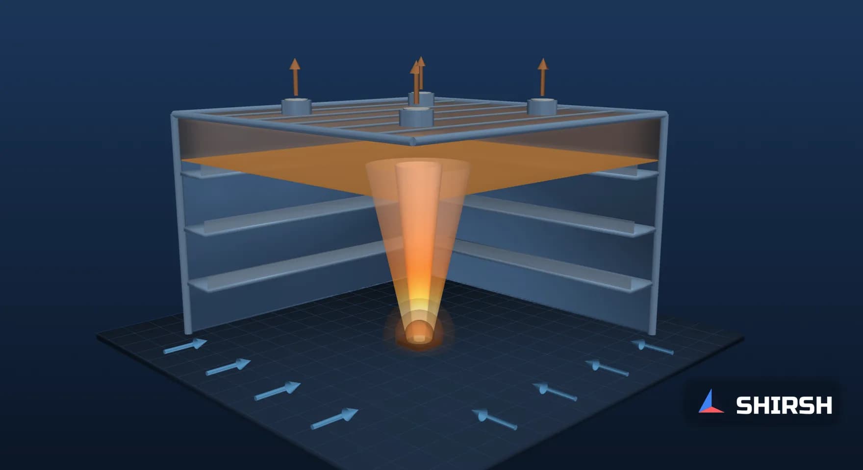
Atrium Smoke Exhaust to NFPA 92: Where Clear Height Gets Expensive
Atrium smoke exhaust is usually sized with the NFPA 92 plume equations, and the answer depends heavily on how high the smoke layer must stay. In a generic 20 m atrium with a 5,000 kW fire, raising the interface from 16 m to 18 m adds less than a fifth to the exhaust but takes the roof from 4 to 26 inlets.
Read the full article below for the methodology, the data, and the engineering decisions behind it.
Atrium smoke exhaust is still sized by hand far more often than by CFD, and for good reason. The NFPA 92 plume equations are short, they have been around for decades, and a spreadsheet gives an exhaust rate in minutes. What the spreadsheet does not show is how sharply that rate depends on two choices the design team makes early: how high the smoke layer must stay, and how many exhaust points the roof can take. This note works through the equations on a generic atrium to show where those choices bite.
1. The equations and where they come from
We used the algebraic set as written out in John Klote's AtriumCalc guide (version 1.1, hosted by ASHRAE, 2015), which states that its equations are consistent with NFPA 92 (2012 edition) and the Smoke Control Handbook, and gives the NFPA 92 section for each. We have not quoted NFPA 92 directly; the section numbers below are the ones the guide cross-references.
Step | Equation (SI) | NFPA 92 (2012) section per the guide |
|---|---|---|
Convective heat release | Qc = χQ, with χ = 0.7 commonly used | 5.5.1.3 |
Limiting elevation (about the mean flame height) | zl = 0.166 Qc^(2/5) | 5.5.1.1 |
Axisymmetric plume mass flow, z ≥ zl | m = 0.071 Qc^(1/3) z^(5/3) + 0.0018 Qc | 5.5.1.1 |
Smoke layer temperature | Ts − T0 = KsQc/(m cp); Ks = 1.0 for exhaust volume, 0.5 for plugholing | 5.5.5 |
Maximum flow to one inlet without plugholing | Vmax = 4.16 γ d^(5/2) ((Ts − T0)/T0)^(1/2), with d/Di > 2 | 5.6.3 |
Minimum spacing between inlets | Smin = 0.9 Ve^(1/2) | 5.6.3, 5.6.8, 5.6.9 |
Here z is height above the base of the fire, d is the depth of the smoke layer below the lowest point of the exhaust inlet, γ is an exhaust location factor and Ve is the flow through one inlet. For the design fire we took the 5,000 kW steady fire that NIST report NISTIR 5516 (Klote, 1994) lists for an atrium with combustibles, along with its 2,000 kW fuel-restricted and 25,000 kW large-fire values.
2. The worked check
The atrium is generic: 30 m by 30 m on plan, 20 m from the fire to the roof, ambient at 20 °C, exhaust inlets in the roof, γ taken as 1.0 as in the guide's worked sample. A/H² is 2.25. With Qc = 3,500 kW the limiting elevation is 4.34 m, so every interface height we tried sits above it and the upper plume equation applies. We set the smoke interface at heights from 6 m to 18 m and computed the plume mass flow at that height, the layer temperature, the volumetric exhaust, the plugholing limit per inlet and the number of inlets that limit implies.
Interface height z, m | Plume mass flow, kg/s | Layer rise, K | Exhaust, m³/s | Layer depth d, m | Vmax per inlet, m³/s | Inlets needed |
|---|---|---|---|---|---|---|
6 | 27.7 | 126.6 | 32.9 | 14 | 1,417 | 1 |
8 | 40.8 | 85.8 | 43.8 | 12 | 794 | 1 |
10 | 56.3 | 62.1 | 56.7 | 10 | 428 | 1 |
12 | 74.1 | 47.2 | 71.4 | 8 | 214 | 1 |
14 | 94.0 | 37.2 | 87.9 | 6 | 92.5 | 1 |
16 | 115.8 | 30.2 | 106.1 | 4 | 30.2 | 4 |
17 | 127.5 | 27.5 | 115.7 | 3 | 14.0 | 9 |
18 | 139.6 | 25.1 | 125.8 | 2 | 4.87 | 26 |

Exhaust rate and the minimum number of roof inlets against the design smoke interface height, 5,000 kW steady fire in a generic 20 m atrium, computed for this note from the NFPA 92 algebraic equations.
3. What the numbers say
The exhaust rate climbs steadily with the interface height because the plume entrains air all the way up. Holding the layer at 16 m needs 3.2 times the exhaust needed at 6 m. That part most designers expect.
The plugholing limit behaves very differently. While the layer is deep it is not a constraint at all; at 10 m one inlet could in principle take 428 m³/s. As the layer thins, the limit falls with d to the power 5/2 and with the shrinking temperature difference. Between a 16 m and an 18 m interface the exhaust rises by less than a fifth, from 106.1 to 125.8 m³/s, while the number of inlets goes from 4 to 26, each carrying no more than 4.87 m³/s and spaced at least 2.0 m apart. The last two metres of clear height are paid for in roof penetrations, ductwork and fans, and a design that asks for them should show the inlet layout alongside the exhaust rate.
The layer temperature tells a related story. At an 18 m interface the layer is only 25.1 K above a 20 °C ambient, and the plugholing check uses half of that. A glazed roof in an Indian summer can sit well above 20 °C on its own, and the algebraic method has no way of knowing that the air under the roof is not at T0.
4. The design fire matters as much as the geometry
At a fixed 10 m interface, the three NISTIR 5516 fires give quite different answers.
Steady design fire | Limiting elevation, m | Exhaust at z = 10 m, m³/s | Layer rise, K |
|---|---|---|---|
2,000 kW, fuel-restricted atrium | 3.01 | 36.7 | 35.5 |
5,000 kW, atrium with combustibles | 4.34 | 56.7 | 62.1 |
25,000 kW, large fire | 8.27 | 146.8 | 149.5 |

Exhaust rate and smoke layer temperature rise at a 10 m interface for the three steady design fires in NISTIR 5516, Table 1, same generic atrium.
The smallest fire needs the least exhaust but gives the coolest layer, which is the case where buoyancy is weakest. The fire size should come from the fuel the atrium will actually hold, with the basis written into the report, since the exhaust scales with it far less than linearly and the layer temperature moves the other way.
5. Where the algebra stops and CFD starts
Each equation above carries an assumption. The plume is axisymmetric and free to entrain on all sides, the smoke layer is uniform, the air under the roof is at ambient, and make-up air arrives gently enough not to push the plume over. NISTIR 5516 also notes that its atrium methods are not appropriate for spaces taller than twice their minimum width. A fire against a wall, a plume spilling from a balcony edge, a roof void warmed by the sun, or make-up air coming through doors near the fire all break one of these, and the guide itself presents its results as starting values for a CFD analysis. For other atrium shapes, the NIST report points to physical modelling or CFD.
In practice we use the algebraic result to set the exhaust rate, inlet count and spacing, and then run CFD on the cases where an assumption is doubtful: the fire position nearest a wall or under a balcony, the summer roof condition, and the make-up air openings. A smoke control report should show both, with the interface height, fire size and γ stated and the inlet layout drawn.
Where Shirsh fits
At Shirsh Technosolutions we check atrium and mall smoke exhaust designs with the NFPA 92 algebraic method and with transient CFD in ANSYS Fluent and OpenFOAM, including plume position, plugholing at the exhaust points and make-up air. If you have an atrium design whose clear height or inlet layout you would like checked before it is built, please get in touch.
References
J. H. Klote, AtriumCalc version 1.1 user guide, ASHRAE, 16 July 2014, updated 3 February 2015: equations (1) to (4), (11), (15) and (17), stated as consistent with NFPA 92 (2012) sections 5.5.1.1, 5.5.1.3, 5.5.5, 5.6.3, 5.6.8 and 5.6.9; Ks of 1.0 for exhaust volume and 0.5 for plugholing; d/Di > 2.
J. H. Klote, Method of Predicting Smoke Movement in Atria with Application to Smoke Management, NISTIR 5516, NIST, November 1994: Table 1 steady design fires (2,000, 5,000 and 25,000 kW); note on spaces taller than twice their minimum width; CFD or physical modelling for other atrium shapes.
NFPA 92, Standard for Smoke Control Systems, 2012 edition (section numbers as cross-referenced in the AtriumCalc guide).
Worked check computed for this note on 19 November 2026: generic 30 m by 30 m atrium, 20 m from fire to roof, ambient 20 °C, χ = 0.7, cp = 1.0 kJ/kg·K, smoke density from the ideal gas law at 101,325 Pa, γ = 1.0. Not any project.
Click to view full size
Related case studies

Want to Apply This to Your Product?
Our engineers can help you implement these techniques on your specific components and assemblies.
Get insights like this in your inbox
Engineering deep-dives, simulation tips, and industry analysis. No spam, unsubscribe any time.