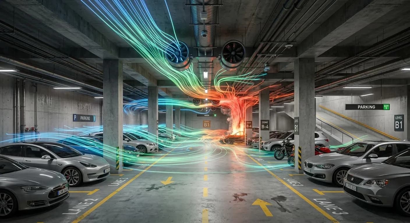
CFD Analysis of Basement Parking Ventilation
Project brief
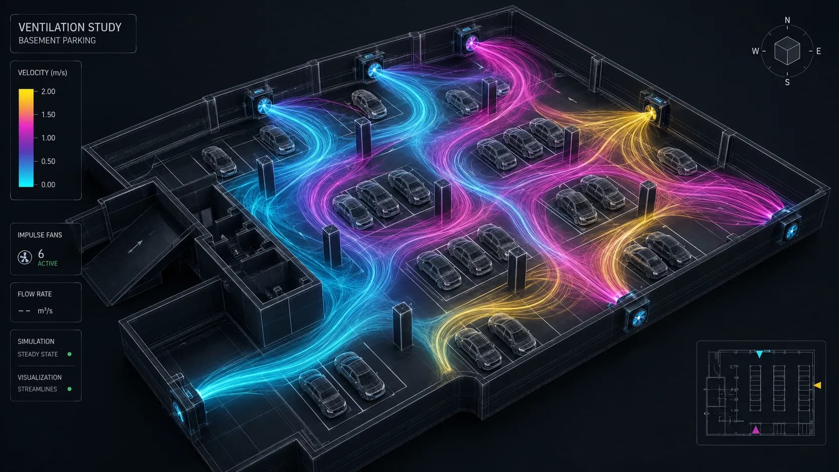
This project evaluates the ventilation performance of an enclosed basement parking facility using three-dimensional CFD. The objective was to verify airflow distribution, exhaust gas removal and optimum CO sensor placement using ANSYS Fluent.
What was at risk
The enclosed basement relied entirely on mechanical ventilation for maintaining indoor air quality. Without adequate airflow, exhaust gases emitted by parked and moving vehicles could accumulate in stagnant regions, creating unsafe conditions for occupants and reducing the effectiveness of the ventilation system.
The client required engineering verification that the proposed ventilation layout could:
• Maintain continuous airflow throughout the basement
• Remove vehicle exhaust gases efficiently
• Eliminate stagnant airflow zones
• Ensure effective extraction through exhaust ducts
• Identify optimum CO sensor locations for continuous monitoring
Solution offered
A complete three-dimensional CFD simulation was performed in ANSYS Fluent to evaluate airflow characteristics and exhaust gas dispersion throughout the basement parking facility.
Instead of relying on simplified ventilation calculations, the complete parking geometry was modeled, including:
• Parking vehicles
• Ramp openings
• Ventilation louvers
• Exhaust ducts
• Vehicle exhaust emission sources
The numerical model solved the Reynolds Averaged Navier-Stokes (RANS) equations using the SST k-ω turbulence model with species transport to accurately predict airflow behavior and contaminant distribution inside the enclosed parking space.
Challenges we overcame
Capturing airflow around parked vehicles and structural obstacles.
Predicting exhaust gas dispersion inside a long and irregular basement layout.
Evaluating airflow at multiple occupant heights.
Verifying exhaust duct effectiveness without physical testing.
Determining practical CO sensor locations using CFD instead of trial-and-error installation.
How we executed
- 1
Step 1: Developed a detailed 3D CFD model of the basement, including ramps, vehicles, columns, louvers, and exhaust ducts, to create the computational fluid domain.
- 2
Step 2: Generated a high-quality Poly-Hex Core mesh with prism layers to accurately capture near-wall airflow while maintaining computational efficiency.
- 3
Step 3: Applied realistic operating conditions by defining vehicle exhaust sources, pressure inlet ramps and louvers, exhaust duct flow rates, and 60% parking occupancy.
- 4
Step 4: Configured a steady-state pressure-based solver with the SST k-ω turbulence model and species transport to simulate airflow and exhaust gas dispersion.
- 5
Step 5: Evaluated airflow distribution, exhaust gas concentration, velocity fields, flow patterns, and optimum CO sensor locations to assess ventilation performance.
Project outcome
Reduced design time by evaluating multiple ventilation layouts through CFD before implementation.
Minimized project cost by reducing the need for physical airflow testing and design modifications.
Optimized the ventilation system design, reducing design cycles and improving engineering efficiency.
Enabled faster engineering decisions using CFD-based airflow and pollutant concentration analysis.
Project gallery
Where this lives
Software used
Related solutions
Industries
At a glance
We apply the same rigour to every engagement
Let us show you what's possible for your product.