
Solar MMS Structure Design, Validation and Verification
Design, validation and verification of solar module mounting structures and their foundations.
What this solution covers
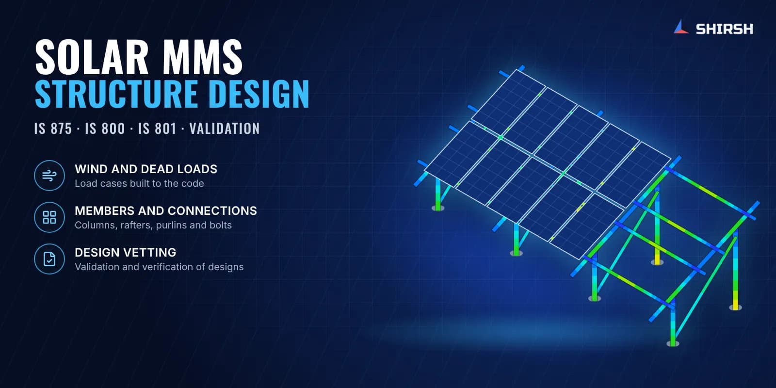
We design solar module mounting structures (MMS) and check designs made by others. The work runs from layout and structural modelling to fabrication drawings and a calculation report, so the structure can be built, erected and defended in review.
Beyond routine design we handle wind studies with CFD, nonlinear FEA of brackets and clamps, pile design with the geotechnical input, and tracker structures. We work to IS 875 for loads, IS 1893 for seismic, IS 800 for hot-rolled steel and IS 801 for cold-formed sections, and to ASCE and Eurocode for overseas projects.
Pain points we address
Structures that fail or deform in service, with costly replacement and downtime
Designs that carry more steel than they need, pushing up the cost per kW
What we solve
Design inconsistencies that cause assembly errors and slow installation
Structures that need frequent maintenance because the design was marginal
Code compliance that a lender or owner's engineer will question
Steel weight per kW that is higher than it should be
Deflection limits not met under wind
Details that are hard to erect at site
More foundations than the layout needs
Parts that are awkward or wasteful to fabricate
How we approach it
- 1
Fabrication drawings prepared to the client's specification
- 2
Structural analysis of the full table for every governing load case
- 3
Pile foundation design to IS codes with the soil data
- 4
FEA of brackets, clamps and connections where hand checks are not enough
- 5
Member sizes optimised for steel weight within the code limits
Deliverables
Fabrication drawings
Structural analysis and calculation reports
Pile foundation design to IS codes
Vetting reports for designs made by others
Code compliance documentation
Expected outcomes
Lower steel consumption through optimised member sizes
Faster installation from accurate fabrication drawings
Structures that hold up to the design loads without repeated repair
A design package that stands up in third-party review
Why Shirsh
Each job starts from a preliminary layout in CAD. We then build the structural model, size the members, run FEA on the critical connections and components, finalise the fabrication drawings and issue the calculation report with the drawing package. For vetting work we check the client's design against the same codes and return a clear list of what passes, what fails and what to change.
Where this lives
Industries served
Software used
Related case studies
CFD and FEA Root-Cause Study of Purlin Defects in a Solar MMS
Root-cause study of purlin defects in a solar MMS, with ANSYS Fluent wind loads mapped into full-table FEA to find which bolted joints actually govern.
ReadThird-Party Design Vetting of a Solar MMS for IS 875 Wind Loading
Independent vetting of a ground-mount solar MMS design to IS 875 Part 3 and IS 801, from wind load placement to member checks, closed round by round.
ReadGround Screw Foundation FEA for a Fixed-Tilt Solar Mounting Structure
Ground screw foundation FEA for a fixed-tilt solar MMS: wind uplift traced from the modules to the screw head in ANSYS, leading to stronger head plates.
ReadVortex Shedding Check of a Ground-Mounted Solar Structure with Wind CFD and Modal FEA
Solar structure vortex shedding check with transient CFD in ANSYS Fluent, CFD wind pressures mapped into FEA and a modal study of a fixed-tilt MMS.
ReadSingle-Axis Solar Tracker CFD and FEA: Wind Pressure Mapping and Structural Qualification
Single-axis solar tracker CFD and FEA: wind pressures at three tilt positions mapped onto a nonlinear ANSYS model, plus an IS 800 pivot bolt check.
ReadRelated insights
Rooftop Solar EPCs: Why Code-Compliant Arrays Still Fail in Wind
Rooftop arrays designed to IS 875 still lose modules in storms, and the EPC is the one called back to site. The code gives one coefficient for the whole array, but the wind does not load a roof that way. Six OpenFOAM cases show where the load really goes, and what an EPC should change before the clamps and anchors are bought.
ReadFour Quiet Ways the IS 875 Wind Load Goes Wrong on a Solar Array
The wind-load calculation almost never fails an audit. It fails the structure. IS 875 (Part 3) is a sound loading code, and the arithmetic in most reports is right. What moves the answer is a handful of small choices in how the code gets applied, and on a light tilted array those small moves decide which members are under-built. Here is the chain done properly, and the four places it usually slips.
ReadWant to learn this?
We also offer ANSYS & SolidWorks training courses.
At a glance
Discuss your project with our engineers
Tell us about your simulation, validation or design challenge.