Seasonal Tilt Solar Mounting Structure FEA for Design Wind and Jack Tilting
FEA of a seasonal-tilt thin-film solar mounting structure to IS 875 and IS 801, covering design wind, jack tilting, bolts and buckling.
Project brief
A utility-scale solar developer wanted a new mounting table for thin-film modules, with a tilt angle that site crews could change through the seasons. The table had a curved tilting link between the rafter and the column, and a jack to swing the module plane to each seasonal angle. Because thin-film modules are mounted in large numbers on light cold-formed members, the developer needed proof that the frame would survive the design wind at site and also stay safe while it was being tilted.
Shirsh Technosolutions carried out the seasonal tilt solar structure FEA in ANSYS Mechanical. We checked the full table under design wind to IS 875 Part 3, checked the cold-formed members to IS 801 and deflections to IS 800, and ran a separate jack operation analysis for the tilting process. Design calculations, fabrication drawings and the bill of materials followed from the same model.
What was at risk
A fixed-tilt table has one geometry to check. A seasonal tilt table does not. The load path runs through a curved tilting link, and it changes when the jack is engaged, so the table has to be safe both when it is locked at an angle and when it is moving.
The members were light-gauge cold-formed sections: hat-section purlins, a C-lip rafter and a rectangular hollow column. Thin walls bring local buckling and reduced effective areas into play, and connection bearing on thin purlins can govern before member stress does.
The developer needed:
a whole-table check for wind acting away from the panels, towards the panels and along the row
member checks for the column, rafter and purlins to the cold-formed steel code, with bolt and deflection checks
a separate check of the frame and tilting link while the jack changes the tilt under working wind
Solution offered
Wind loads to IS 875 Part 3. We worked out the design wind pressure from the basic wind speed with the risk, terrain and topography factors, and applied net pressure coefficients for a free-standing panel. Three wind cases were set up: uplift acting away from the panels, wind pushing towards the panels and wind along the length of the table. Each was combined with dead load of the structure and the modules.
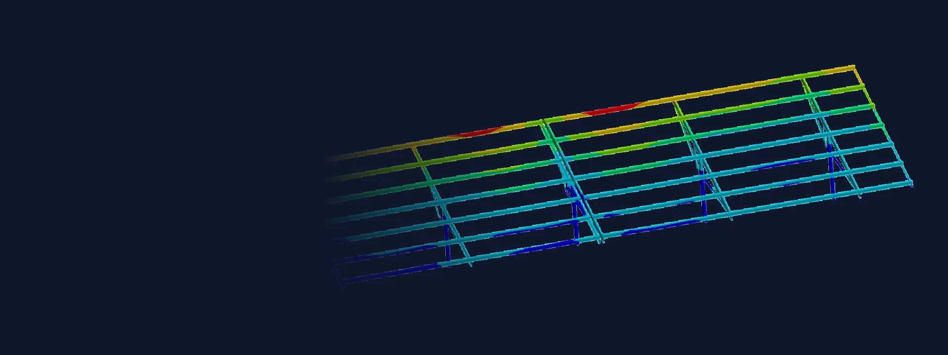
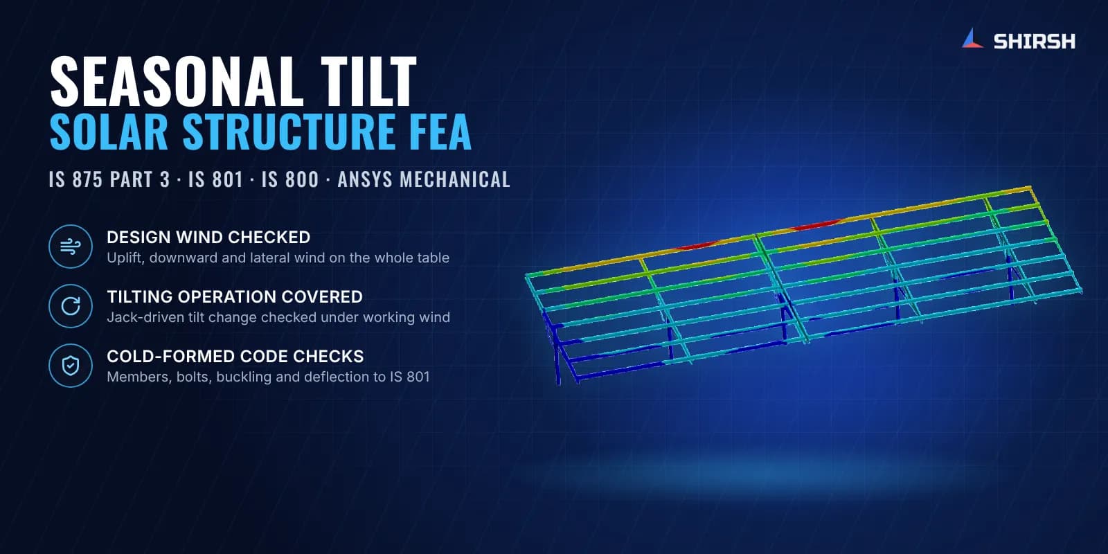
Full-table FE model in ANSYS Mechanical. The purlins, rafters, columns, bracing and curved tilting links were modelled with shell and solid elements, so the stresses in thin cold-formed walls and at the link came out directly. Columns were braced along the row and the bases restrained as in the design. The model gave stresses, deformations and support reactions for every load combination.
Cold-formed member and connection checks. The column was checked for axial compression and combined axial and bending to IS 801. Rafter and purlins were checked for bending, shear and combined bending and shear, using effective section properties for the thin walls. Bearing was checked for the purlin-to-module clamp, purlin-to-rafter and rafter-to-column bolts, and a linear buckling analysis confirmed the table is stable under the governing wind. Member deflections were compared with the IS 800 limits.
Jack operation analysis. For the tilting process we built a single-frame model carrying the panel mass, with the jack force applied at the rafter and the column restrained at its base. The frame, the tilting link and the purlins were checked at a range of working wind speeds, so the developer knows the frame stays within limits while the tilt is being changed.
Design package and review. The structure passed the stress, deflection, buckling and bolt checks under the design wind, and the jack operation cases stayed well inside the allowable stress and deflection limits. After the developer's engineering review we updated the purlin clamp positions, rectified the reports and issued drawings and the bill of materials. A variant of the same table carrying a robotic module cleaner was checked the same way.
Common questions
Why does a seasonal tilt solar structure need a separate jack operation analysis? While the jack is changing the angle, the rafter is carried through the jack and the tilting link instead of its locked connection. The load path is different, so the frame and link must be checked for that state under the wind speed allowed during tilting.
Which codes apply to a cold-formed steel solar mounting structure in India? Wind loads come from IS 875 Part 3. Thin cold-formed members such as hat purlins and C-lip rafters are checked to IS 801, and deflections are usually compared with the limits in IS 800. FEA gives the stresses and reactions that these checks need.
Challenges we overcame
A table whose geometry and load path change with the seasonal tilt
A separate load path through the jack and tilting link while the tilt is changed
Light-gauge cold-formed members where local buckling and effective area matter
Bolt bearing on thin purlin and rafter walls
Uplift, downward and along-row wind all needing their own checks
How we executed
- 1
Reviewed the table concept, the member sections and the tilting arrangement
- 2
Calculated design wind pressure and net pressure coefficients to IS 875 Part 3
- 3
Built a full-table shell and solid FE model in ANSYS Mechanical
- 4
Solved dead load with uplift, downward and along-row wind combinations
- 5
Checked the column, rafter and purlins to IS 801 using effective section properties
- 6
Checked bolt bearing at the clamp, purlin and rafter connections and ran a linear buckling analysis
- 7
Compared member deflections with the IS 800 limits and reported support reactions
- 8
Analysed a single frame during jack operation at a range of working wind speeds
Project outcome
The full table met the IS 801 stress checks and the IS 800 deflection limits under the design wind.
Linear buckling and bolt bearing checks confirmed the frame and its connections for the governing wind case.
The jack operation analysis showed the frame and tilting link stay well within limits while the tilt is changed under working wind.
Purlin clamp positions were updated after the developer's review and drawings and the bill of materials were issued from the checked design.
Project gallery
Where this lives
Software used
Related solutions
Industries
At a glance
We apply the same rigour to every engagement
Let us show you what's possible for your product.