
IMDAS Frame Designer
An integrated design and simulation software for static and dynamic analysis.
Official websiteAbout IMDAS Frame Designer
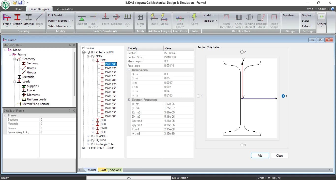
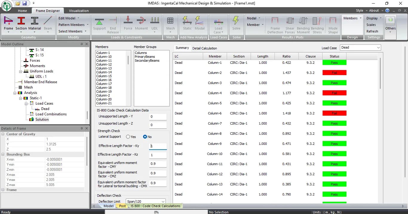
IMDAS Frame Designer provides a structural modeling environment where users can create and analyze steel frame structures. It supports defining geometry, assigning materials, applying loads, and performing structural analysis. The interface includes tools for editing models, applying constraints, and solving static and modal analyses. it leverages the Code Aster solver for advanced finite element analysis, ensuring accurate and reliable structural simulations for engineering applications.
Key features
Solar Structure Wizard : Automate design of ground and roof top solar panel frame structures.
Bolt Connection Check: Performs connection design as per IS 800 & IS 801 standards.

Capabilities
Static Structural Analysis
Modal Analysis to determine mode shapes and assess dynamic behavior to avoid resonance.
Seismic Analysis: Determines seismic loads as per IS 1893 and applies appropriate load combinations automatically.
Applications
Steel Structure Design
Pre-Engineered Steel Structures
Skid structures
EOT , Jib Crane structures
Ground and roof top solar panel frame structures
Carport steel structres
Target users
Target users
Articles featuring this tool
Why Single-Axis Solar Trackers Need FEA, CFD, and Aeroelastic Analysis — Not Just IS 875
A single-axis solar tracker can clear every line of IS 875, pass its STAAD model, and still fail in a windstorm that never reached the code design speed. The reason is uncomfortable but simple: the code hands you a static pressure, and the structure that tore apart was responding to a dynamic, fluid-structure problem the code was never written to see. This is sharpest with single-axis trackers, which behave less like a stiff steel frame and more like a bridge deck on a torsional spring. Here is where IS 875 stops, where FEA and CFD pick up, and why "passes the code" and "survives the wind" are two different questions.
ReadWhy Fixed-Tilt Ground-Mount Solar Structures Fail
Fixed-tilt ground-mount is the structure everyone treats as solved. No moving parts, a straight load path from module to rail to post to ground, a static wind check, done. That reputation for simplicity is precisely why these structures fail — not from exotic physics, but from foundations pulled out of the soil, connections detailed for the wrong load direction, slender members that buckled under uplift, and corners that saw far more wind than a borrowed coefficient ever admitted. Walk the load path with a failed array in front of you and the causes are rarely mysterious. Here is how to read the damage, and the analysis chain that would have caught it on paper.
ReadHow to Check a Cold-Formed Solar Mounting Structure to IS 801: A Step-by-Step Guide
Most ground-mounted solar structures in India are made from cold-formed steel — thin steel sheet bent into channels and hat sections. Engineers find the wind load from IS 875 Part 3, then check the steel using IS 801. Two mistakes are very common. First, engineers use the full cross-section, but thin steel does not work that way — part of it buckles early, so the code makes you use only the "effective" part. Second, engineers check only the steady (static) load and skip the moving (dynamic) effects. This guide explains both problems in simple steps. It then checks the four main members of a solar structure — post, rafter, bracing, and a 1 mm hat purlin — with full numbers, so you can see exactly where the common shortcuts go wrong.
ReadFour Quiet Ways the IS 875 Wind Load Goes Wrong on a Solar Array
The wind-load calculation almost never fails an audit. It fails the structure. IS 875 (Part 3) is a sound loading code, and the arithmetic in most reports is right. What moves the answer is a handful of small choices in how the code gets applied, and on a light tilted array those small moves decide which members are under-built. Here is the chain done properly, and the four places it usually slips.
ReadNeed expert help with this tool?
Our certified engineers set up, configure and run simulations — validated results without the learning curve.
Where it fits
At a glance
We help you pick the right license
From single-seat to enterprise — configured for your workload.