
CFD and FEA Root-Cause Study of Purlin Defects in a Solar MMS
Root-cause study of purlin defects in a solar MMS, with ANSYS Fluent wind loads mapped into full-table FEA to find which bolted joints actually govern.
Project brief
A supplier of cold-formed solar structure components found defects in the hat purlins it had delivered for a utility-scale solar plant. Grinding off the burrs at the punched holes had thinned the purlin locally, and the cut ends showed a slight flare that changed the hole spacing. With the structure already on site, the supplier, the EPC and the owner needed to know one thing: if a table fails in a storm, would it be because of a connection, a manufacturing defect or the design itself?
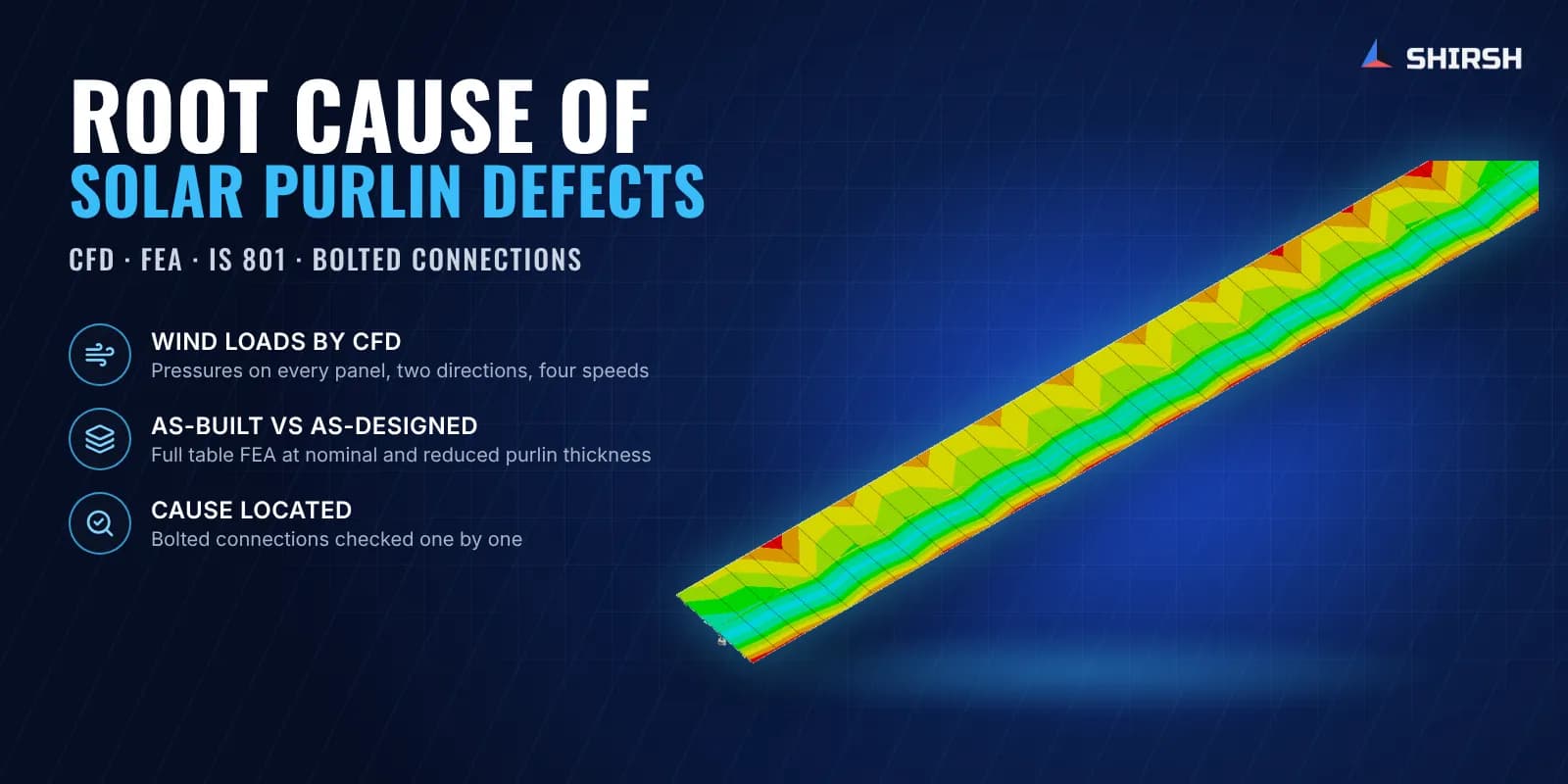
Shirsh Technosolutions answered that with simulation. We calculated the wind loads on the full table by CFD in ANSYS Fluent, mapped them into a finite element model of the complete structure in ANSYS Mechanical, and checked every bolted connection and the purlin member at both the nominal and the reduced thickness.
What was at risk
A thin cold-formed purlin is sensitive to small changes. A few hundredths of a millimetre lost at the holes reduces bearing capacity right where the bolts transfer load, and in a site dispute it is tempting to blame every problem on that loss. The client asked us to keep the causes apart and say plainly which one governs.
That needed real wind loads, not a code pressure spread evenly over the table, because the critical connections depend on where the pressure peaks and how it reverses between downwind and upwind. It also needed a model detailed enough to carry load through each bolted joint, from panel to purlin, purlin to rafter, rafter to column and bracing to plate, so that every connection could be checked in its own right.
Solution offered
Wind loads by CFD. We built the full table, panels, purlins, rafters, bracing and columns, inside a large air domain in ANSYS Fluent.
RANS with the k-omega SST model, and a poly-hexcore mesh with inflation layers on the panel and member surfaces.
An atmospheric velocity profile at the inlet from the one-seventh power law, a pressure outlet, and symmetry on the side and top walls.
Downwind and upwind directions at four wind speeds, from the design speed down to light wind.
Transient runs to find the vortex shedding frequency at points along the table, using the Strouhal number.
Structural check by FEA. The panel and member pressures were mapped directly onto a finite element model of the whole table in ANSYS Mechanical. Each member joint was modelled with bolt elements, and the panels were tied to the purlins so that they passed load without adding stiffness. Self weight came from the material densities, and the column bases were fixed.
We solved the upwind and downwind cases twice, once with the purlin at its nominal thickness and once at the reduced, as-manufactured thickness. Every bolted connection was then checked to IS 801 for bolt shear, bearing and end distance, and the purlin members were checked to IS 801 for bending, web shear and local buckling of the flanges, web and lips.
Common questions
Why use CFD wind loads instead of IS 875 pressures for a failure study? Code coefficients give a safe envelope for design. A root-cause study has to reproduce how the actual table is loaded, including where the pressure peaks on the panel and how it changes between downwind and upwind. CFD gives that distribution, and mapping it into FEA puts the right load into each connection.
Does a small loss in purlin thickness cause failure? Not on its own. In this study the purlin members passed their member checks at both the nominal and the reduced thickness, while one connection was overstressed in both cases. The thickness loss mattered locally around the bolt holes, but the governing problem sat in the connection detail.
Challenges we overcame
Separating connection, manufacturing and design causes in a dispute between site parties
Wind loads that reverse between downwind and upwind and peak at different parts of the table
A purlin only a little thinner than designed, compared like for like with the nominal section
Load transfer through many small bolted joints in a full table model
Results that had to stand up to a supplier, an EPC and an owner at the same time
How we executed
- 1
Reviewed the drawings, the supplier's defect report, site photographs and thickness measurements
- 2
Built the full table model and the CFD domain, and meshed it with inflation layers at the surfaces
- 3
Ran steady CFD for downwind and upwind at four wind speeds, and transient CFD for vortex shedding
- 4
Mapped the CFD pressures onto a full finite element model with bolt elements at every joint
- 5
Solved upwind and downwind cases at nominal and reduced purlin thickness
- 6
Checked every bolted connection and the purlin members to IS 801
- 7
Reported the governing connection and the effect of the thickness loss
Project outcome
Pressure was highest on the top face of the panels in downwind and on the bottom face in upwind, with upwind governing the bolt checks.
The purlin members passed the IS 801 member check at both thicknesses, with local stress raised only around the bolt holes.
The column-to-plate connection was overstressed at both the nominal and the reduced purlin thickness, which placed the main problem in the connection detail and not in the thickness loss.
The client received a clear classification of the cause, backed by CFD and FEA, to settle the site question and plan the fix.
Project gallery
Where this lives
At a glance
We apply the same rigour to every engagement
Let us show you what's possible for your product.