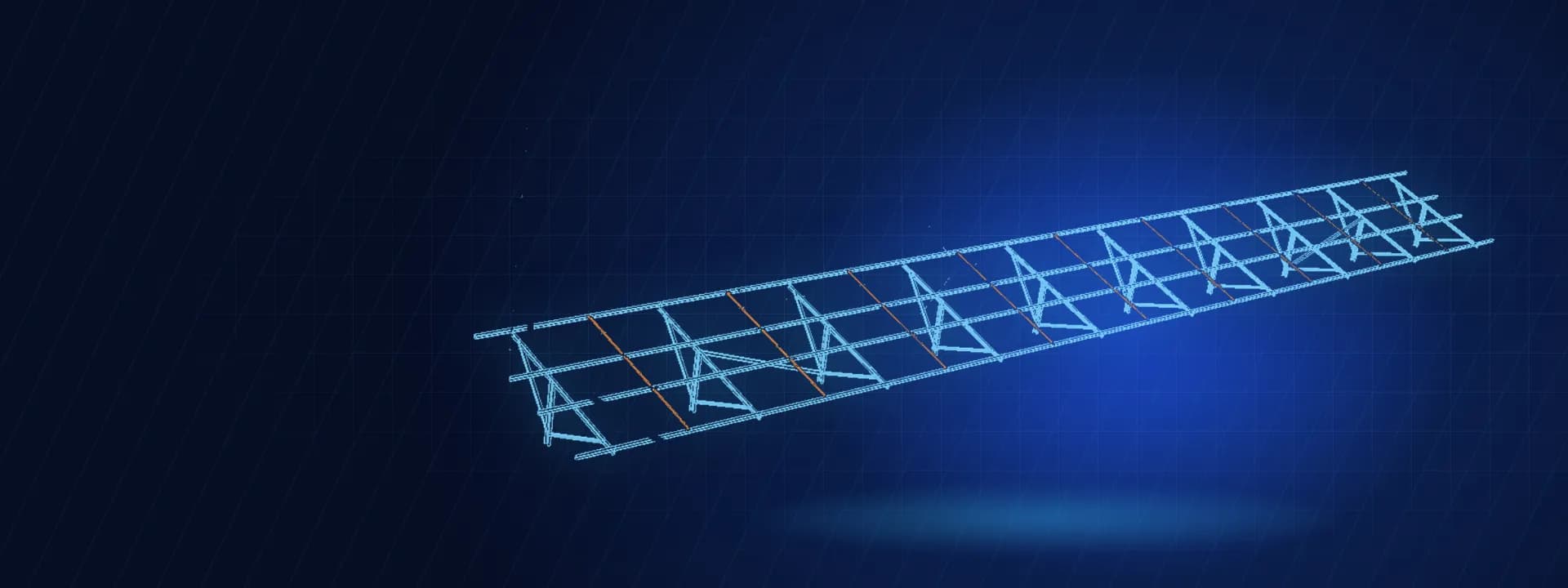
Third-Party Design Vetting of a Solar MMS for IS 875 Wind Loading
Independent vetting of a ground-mount solar MMS design to IS 875 Part 3 and IS 801, from wind load placement to member checks, closed round by round.
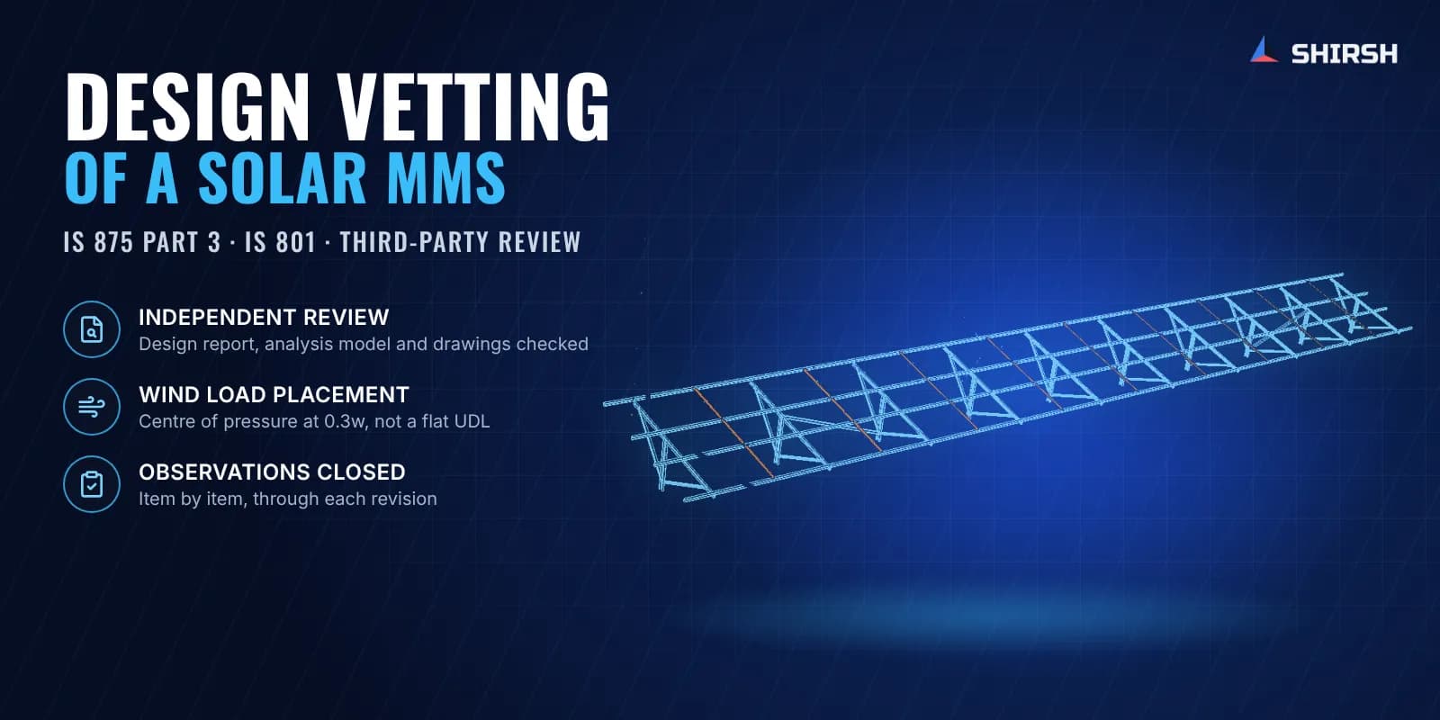
Project brief
The owner's engineer for a ground-mount solar plant asked Shirsh Technosolutions to vet the module mounting structure design submitted by the EPC's design team. The table was a two-in-portrait fixed-tilt structure in cold-formed steel, designed to IS 875 Part 3 for wind and IS 801 for the members. The owner side had the design report, the analysis model and the drawings, but no in-house team to check them line by line.
We reviewed the design basis, prepared our own IS 875 wind load calculation, and checked the analysis model against the general arrangement drawing. Our observations went back as a marked-up report with a comments sheet, and we stayed on through the revised submissions until each point had an answer.
What was at risk
A fixed-tilt solar table is light, long and exposed, so wind governs almost every member. How that wind is placed on the table matters as much as how large it is. The design report quoted the IS 875 Part 3 rule that the centre of pressure acts at 0.3w from the windward edge, yet the analysis model applied the wind as a uniform load across all purlins. With a uniform load, the windward purlins, the rafter and the front column all see less than the code distribution gives them.
The owner's engineer also needed to know whether the model matched what would be built. A design report can pass every unity check and still be checking a different structure, if a column length, a section or its properties were entered wrongly. Any such gap had to be found on paper, before steel was rolled and piles were driven.
Solution offered
We started from the loads. Our own IS 875 Part 3 calculation was set up twice, once with uniform pressure on the panel and once with the pressure varying across the table so that its resultant sits at 0.3w from the windward edge. The second case moves a much larger share of the load onto the windward purlins and the members below them.
We then went through the design report and the analysis model against the drawings. The first round of observations covered:
Wind loading to be changed from uniform to varying load per IS 875 Part 3, with the sections resized accordingly.
Wind forces on the rafters to be added in both horizontal directions.
A column length in the model that did not match the general arrangement drawing.
The column deflection limit to be taken as height/240.
Bracing members failing the unity check even under the uniform load.
Column section area and section properties to be checked, with the property calculations included in the report.
Section property input for the cold-formed angle and channel members that did not match the calculated values, with the offset entered against the wrong axis.
The designer corrected the geometry, deflection and section items in the next revision and argued that the uniform load had been agreed in the technical specification. We held the point and asked for the bracing check to be re-run in the current version of the analysis software, where it still failed. After a joint meeting, the EPC submitted two complete designs, one with uniform load and one with the varying load, so that the developer could choose with both results in front of it. Our final round compared the two and flagged a column section that differed between the model and the member calculation in the varying-load design.
Common questions
Why does the IS 875 centre of pressure at 0.3w matter for solar structures? On a tilted panel the wind pressure is not uniform. It is highest near the windward edge, and IS 875 Part 3 places the resultant at 0.3w from that edge. Applying the same total load as a uniform pressure spreads it evenly over all purlins, so the windward purlins, rafter and front column are designed for less than they will see.
What does third-party design vetting of a solar MMS include? A check of the design basis and loads, an independent wind load calculation, a comparison of the analysis model with the drawings, member and connection checks against the code, and a written list of observations. The vetting engineer then reviews each revision until every observation is either corrected or formally accepted by the owner.
Challenges we overcame
Wind applied as a uniform load although the design report itself quoted the 0.3w rule
Analysis model geometry that did not match the general arrangement drawing
Bracing members failing the code check even under the lighter uniform load
Section property input errors in cold-formed angle and channel members
A contractual argument for uniform load that had to be answered with engineering, not opinion
How we executed
- 1
Reviewed the design basis report, analysis model, drawings, module data and geotechnical input
- 2
Prepared an independent IS 875 Part 3 wind load calculation with uniform and varying pressure
- 3
Checked model geometry, supports and section properties against the drawings
- 4
Checked deflection limits and member unity ratios for columns, rafters, purlins and bracing
- 5
Issued a marked-up report and a comments sheet with each observation
- 6
Reviewed the designer's replies and revised submissions, and re-checked open items
- 7
Compared the uniform-load and varying-load designs submitted after the joint meeting
Project outcome
Errors in column length, section properties and the deflection limit were found on paper and corrected in the next revision.
Failing bracing members were identified and sent back for a fresh check in the current software version.
The varying-load design to IS 875 Part 3 was produced alongside the uniform-load design, so the developer could take the decision on engineering grounds.
The owner's engineer received a written record of every observation, reply and closure across three rounds.
Project gallery
Where this lives
At a glance
We apply the same rigour to every engagement
Let us show you what's possible for your product.