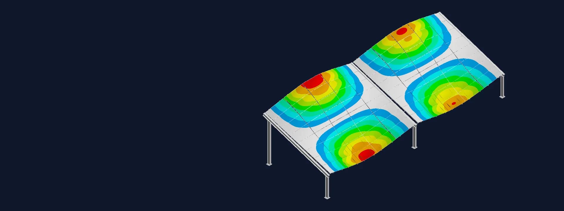
Cable-Supported Solar Structure CFD and FEA: Vortex Shedding and Resonance Check
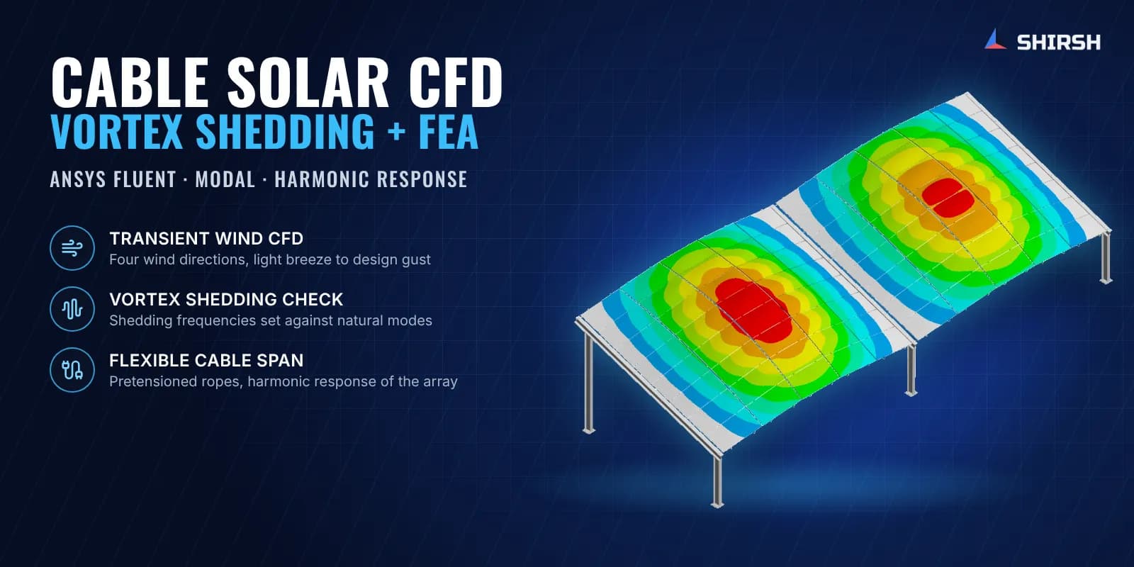
Cable-supported solar structure CFD and FEA: transient wind CFD finds vortex shedding, then modal and harmonic FEA checks the flexible span for resonance.
Project brief
A developer of cable-supported solar mounting systems was planning a narrow canal-top installation, with the module rows hung on pretensioned ropes between end columns. The module manufacturer was not comfortable with a flexible support. Its questions were about fluctuating wind pressure, suction on the back of the modules, wind from every direction and the chance of wind-induced resonance. The developer needed an independent engineering answer to take back to them.
Shirsh Technosolutions carried out a combined cable-supported solar structure CFD and FEA study. Steady and transient CFD in ANSYS Fluent gave the pressure on the panels and the vortex shedding frequencies. The pressures were mapped into ANSYS Mechanical, where a modal and harmonic response analysis of the rope-supported array checked whether those frequencies could excite the structure.
What was at risk
A fixed-tilt table on rigid purlins is stiff, and the usual design pressures for solar modules are written for that case. A rope-supported span is different. It is light, it sags under its own weight, and it has many closely spaced natural frequencies, some of them low. Wind passing over a tilted panel row sheds vortices from its edges, and the frequency of that shedding rises with wind speed. Somewhere between a light breeze and the design gust the two can meet.
A static wind check would miss this completely. The developer needed to know at which speeds and wind directions the shedding frequency comes close to a natural frequency of the span, whether those modes actually move a large share of the mass, and what that does to the modules and their clamps.
Solution offered
CFD model of the array. We built the external flow domain around the client's 3D model of the panel rows, rafters and columns, sized for external aerodynamics. A poly-hexcore mesh with inflation layers on the panel surfaces captured the boundary layer. The approaching wind used a one-seventh power-law velocity profile, and turbulence was modelled with k-omega SST.
Wind from four directions at four speeds. Downwind, upwind, side wind and 45 degree upwind cases were each run from a light wind up to the regional design wind speed. Steady runs gave the pressure and velocity fields on the top and bottom faces of the modules. Transient runs recorded the flow at six points around the array, and the frequency spectrum at each point gave the Strouhal number and the vortex shedding frequency for that case.
Structural model with pretensioned ropes. In ANSYS Mechanical the glass modules, aluminium frames, rafters and columns were modelled with shell and solid elements, and the ropes were pretensioned before any other load. The CFD pressures were mapped onto the panels, and the self-weight sag of the span was checked first.
Modal analysis and resonance screen. A modal analysis extracted several hundred natural frequencies with their mass participation. Each vortex shedding frequency was placed against the nearest natural frequency to list the wind cases where resonance was possible.
Harmonic response at the matched frequencies. For every near match, a harmonic response analysis showed how the span deforms and where the stresses build up. The clamping region on the module frame came out as the area to watch.
Winglet follow-up. The client then added winglets to the rows, and we repeated the CFD with the new geometry. Most of the remaining near matches involved modes with very little mass participation. One mode that moves a large share of the mass still lined up with a shedding frequency, so we recommended external tensioning members at the ends of the structure.
Common questions
Can wind cause resonance in a cable-supported solar structure? It can. Wind shedding vortices off a tilted panel row creates a fluctuating force whose frequency rises with wind speed. A rope-supported span has many low natural frequencies, so transient CFD and modal FEA are used together to find the speeds and directions where the two coincide.
How is vortex shedding frequency found by CFD for solar panels? Transient CFD records the pressure or velocity at points around the array over time. A frequency analysis of that signal gives the dominant frequency and the Strouhal number, which is then compared with the natural frequencies from a modal analysis of the structure.
Challenges we overcame
A light, rope-supported span with many closely spaced low natural frequencies
Module manufacturer concerns about fluctuating wind, back-side suction and resonance on a flexible support
Wind from four directions at four speeds, each needing its own transient CFD run
Linking CFD pressures and shedding frequencies to a pretensioned structural model
Separating near matches that matter from those with negligible mass participation
How we executed
- 1
Built the CFD domain around the client's 3D model of the panel rows and supports
- 2
Meshed with poly-hexcore cells and inflation layers, applied a power-law wind profile
- 3
Ran steady CFD for panel pressure and velocity in four wind directions
- 4
Ran transient CFD at four wind speeds and read shedding frequencies at six points
- 5
Modelled modules, frames, rafters, columns and pretensioned ropes in ANSYS Mechanical
- 6
Mapped the CFD pressures and checked the self-weight sag of the span
- 7
Ran modal analysis and screened every shedding frequency against the natural modes
- 8
Ran harmonic response at each near match, then repeated the CFD with winglets added
Project outcome
The developer got a wind case by wind case map of where vortex shedding comes close to a natural frequency of the flexible span.
Harmonic response showed how the array moves at those frequencies and pointed to the module clamping region as the area to watch.
With winglets, most remaining near matches involved modes with very little mass participation, and one significant mode was identified clearly.
External tensioning members at the ends were recommended, and the client's later revision added a tension transfer cable, stabiliser struts and winglets.
Project gallery
Where this lives
At a glance
We apply the same rigour to every engagement
Let us show you what's possible for your product.