
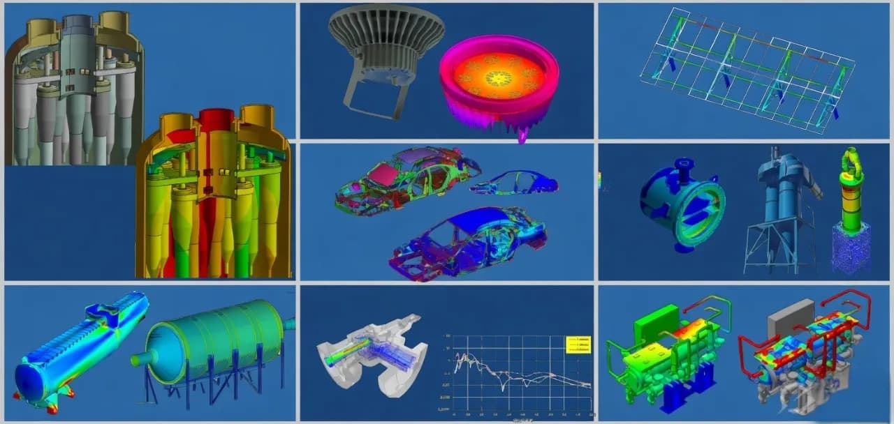
Structural Finite Element Analysis (FEA)
Comprehensive finite element analysis services for structural integrity, fatigue life, and design optimization of industrial components and assemblies.
What this solution covers
Pain points we address
Physical prototypes fail during testing, causing project delays and cost overruns
Lack of in-house FEA expertise to validate designs against customer specifications
Uncertainty about fatigue life and long-term structural reliability under service loads
Designs are over-engineered due to insufficient understanding of actual stress distributions
What we solve
Structural adequacy assessment against applicable design codes (ASME, EN, IS)
Fatigue life prediction under constant and variable-amplitude loading
Nonlinear contact, large deformation, and material plasticity analysis
Dynamic response evaluation — modal, harmonic, random vibration, and seismic
How we approach it
- 1
Geometry preparation: import native CAD from SolidWorks, perform defeaturing and mid-surface extraction for shell elements
- 2
Mesh generation: structured hex meshing for critical regions, automatic tetrahedral meshing with convergence studies
- 3
Boundary conditions: apply realistic constraints and loading from test data, load spectra, or code-specified combinations
- 4
Solution and post-processing: run ANSYS Mechanical solver with appropriate nonlinear controls, extract von Mises stress, fatigue damage, and safety factors
- 5
Reporting: deliver engineering report with methodology, assumptions, results interpretation, and design recommendations
Deliverables
FEA methodology document with assumptions and boundary condition rationale
Detailed results report with stress/deformation contour plots and safety factor mapping
Fatigue life report with damage fractions and critical location identification
Design improvement recommendations with supporting parametric study data
ANSYS Mechanical project files for client internal review and future reanalysis
Expected outcomes
Reduction in physical prototyping iterations by 40-60% through virtual testing
Design sign-off confidence backed by code-compliant FEA evidence
Weight reduction of 15-25% through stress-driven topology and parametric optimization
Accelerated development timelines by identifying failure modes early in the design cycle
Why Shirsh
Our engineers bring deep domain expertise in structural mechanics, material behavior, and industry code compliance. We don't just run simulations — we interpret results in the context of manufacturing feasibility, code requirements, and operational reality, delivering actionable engineering recommendations rather than raw contour plots.
Where this lives
Related case studies
3D Transient Thermal Simulation of Multi Layer Valve Welding
A high fidelity thermal analysis verifying soft-seal integrity during an accelerated 8-layer welding sequence on a 16-inch Class 900 Trunnion Mounted Ball Valve
ReadAdvanced Explicit Dynamic Hail Impact Modeling on High-Frequency Aerospace Radomes
Utilizing high-velocity transient impact simulation to analyze progressive composite degradation and multi-strike damage tolerance on a aircraft radome.
ReadFatigue Life Prediction of Heavy Machinery Mounts
Nonlinear FEA-based fatigue assessment of elastomeric vibration isolators on a mining excavator, extending validated service life from 8,000 to 14,000 operating hours.
ReadRelated insights
Why Single-Axis Solar Trackers Need FEA, CFD, and Aeroelastic Analysis — Not Just IS 875
A single-axis solar tracker can clear every line of IS 875, pass its STAAD model, and still fail in a windstorm that never reached the code design speed. The reason is uncomfortable but simple: the code hands you a static pressure, and the structure that tore apart was responding to a dynamic, fluid-structure problem the code was never written to see. This is sharpest with single-axis trackers, which behave less like a stiff steel frame and more like a bridge deck on a torsional spring. Here is where IS 875 stops, where FEA and CFD pick up, and why "passes the code" and "survives the wind" are two different questions.
ReadWhy Fixed-Tilt Ground-Mount Solar Structures Fail
Fixed-tilt ground-mount is the structure everyone treats as solved. No moving parts, a straight load path from module to rail to post to ground, a static wind check, done. That reputation for simplicity is precisely why these structures fail — not from exotic physics, but from foundations pulled out of the soil, connections detailed for the wrong load direction, slender members that buckled under uplift, and corners that saw far more wind than a borrowed coefficient ever admitted. Walk the load path with a failed array in front of you and the causes are rarely mysterious. Here is how to read the damage, and the analysis chain that would have caught it on paper.
ReadHow to Check a Cold-Formed Solar Mounting Structure to IS 801: A Step-by-Step Guide
Most ground-mounted solar structures in India are made from cold-formed steel — thin steel sheet bent into channels and hat sections. Engineers find the wind load from IS 875 Part 3, then check the steel using IS 801. Two mistakes are very common. First, engineers use the full cross-section, but thin steel does not work that way — part of it buckles early, so the code makes you use only the "effective" part. Second, engineers check only the steady (static) load and skip the moving (dynamic) effects. This guide explains both problems in simple steps. It then checks the four main members of a solar structure — post, rafter, bracing, and a 1 mm hat purlin — with full numbers, so you can see exactly where the common shortcuts go wrong.
ReadFour Quiet Ways the IS 875 Wind Load Goes Wrong on a Solar Array
The wind-load calculation almost never fails an audit. It fails the structure. IS 875 (Part 3) is a sound loading code, and the arithmetic in most reports is right. What moves the answer is a handful of small choices in how the code gets applied, and on a light tilted array those small moves decide which members are under-built. Here is the chain done properly, and the four places it usually slips.
ReadWant to learn this?
We also offer ANSYS & SolidWorks training courses.
At a glance
Discuss your project with our engineers
Tell us about your simulation, validation or design challenge.