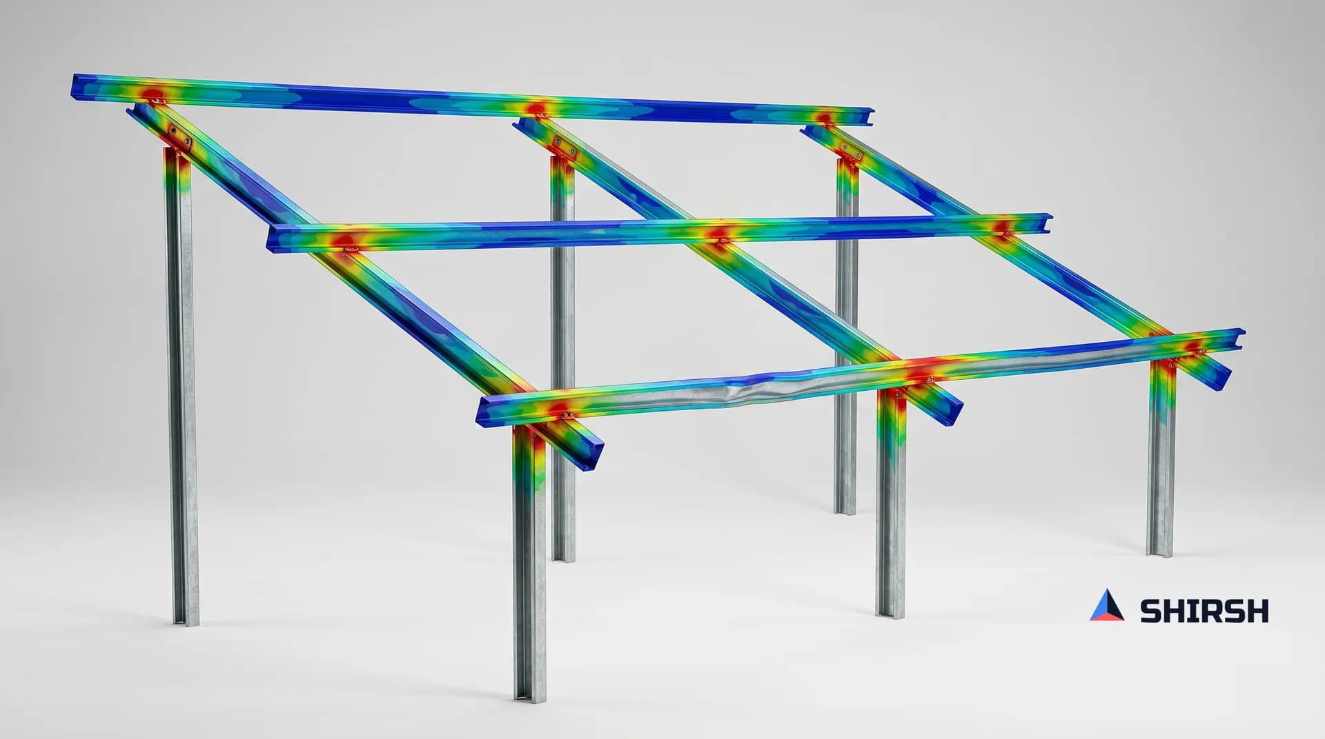
How to Check a Cold-Formed Solar Mounting Structure to IS 801: A Step-by-Step Guide
Most ground-mounted solar structures in India are made from cold-formed steel — thin steel sheet bent into channels and hat sections. Engineers find the wind load from IS 875 Part 3, then check the steel using IS 801. Two mistakes are very common. First, engineers use the full cross-section, but thin steel does not work that way — part of it buckles early, so the code makes you use only the "effective" part. Second, engineers check only the steady (static) load and skip the moving (dynamic) effects. This guide explains both problems in simple steps. It then checks the four main members of a solar structure — post, rafter, bracing, and a 1 mm hat purlin — with full numbers, so you can see exactly where the common shortcuts go wrong.
Read the full article below for the methodology, the data, and the engineering decisions behind it.
Why this guide
Almost every solar mounting structure (MMS) is designed the same way. You take the basic wind speed from IS 875 Part 3. You work out the wind pressure. You put the load on the frame. You check each member against IS 801. The software shows "pass," and the design is done.
This method is correct in outline. But two things inside it often go wrong. Both come from the same fact: cold-formed steel does not behave like the hot-rolled steel most of us studied first.
Mistake 1: using the full section. Cold-formed steel is thin. A thin flat plate buckles (folds locally) at a low stress, long before the steel reaches its yield strength. So the full width of the plate does not carry load. IS 801 makes you use a smaller "effective width" instead. If you use the full section, you think the member is stronger than it really is.
Mistake 2: checking static load only. A solar array stands in open wind. The wind is not steady — it gusts, it shakes the structure, and over years it causes fatigue. IS 801 says this directly. Clause 1.1 allows the code for non-building structures only if you "make appropriate allowance for dynamic effects." Most designs never add this allowance.
We will return to both points in the examples.
A few terms, in plain words
Cold-formed steel: thin steel sheet, bent cold into a shape (channel, hat, angle). Thickness is usually 1 to 3 mm.
(yield strength): the stress at which steel starts to deform permanently.
ratio: the flat width of a plate element divided by its thickness. A large w/t means a wide, thin plate. Such a plate buckles easily.
Effective width: after part of a thin plate buckles, only a strip near the edges keeps carrying load. That working strip is the effective width.
Section modulus (S): a number that tells how strong a section is in bending. Larger S means more bending strength.
Moment of inertia (I): a number that tells how stiff a section is. Larger I means less deflection.
The basic rules you need
IS 801 is a working-stress code from 1975. It uses MKS units. Keep these in mind:
Work in kgf and cm. Stress is in. The steel's stiffness is .
The allowable stress is . This is the highest stress the code allows. The safety factor is about 1.67.
This is working stress design. Do not add the load factors from IS 800. IS 800 uses a different method (limit state). Mixing the two is wrong.
Effective width formula (for a stiffened plate in compression):
. The plate is fully effective only up to . Here b is the effective width and f is the stress in the plate.
A note on the wind increase. IS 801 Clause 6.1.2 allows a higher allowable stress for wind. You may use a stress 33⅓% higher when wind or earthquake acts alone (6.1.2.1). You may also use it for a wind-plus-other-load combination (6.1.2.2), but only if the section is still not smaller than the dead-load-plus-live-load case needs. This rule comes from the old working-stress method. Modern practice (IS 800:2007 and most reviewers) has largely stopped using it. So in this guide we do not use the increase. Every check uses the basic allowable . If you choose to use the increase, apply it carefully and follow the 6.1.2.2 condition.
A note on units. IS 875 gives wind pressure in N/m² (newtons). IS 801 formulas use kgf and cm. Finish the wind calculation in SI units. Then convert to kgf and cm before you use any IS 801 formula. Do not mix the two halfway. (Useful: , and .)
The four members
These are the real sections, for a 44 m/s wind zone:

One point to remember: thin solar sections often use high-strength steel (grades like G550). A higher gives a higher allowable stress. But it also makes the effective-width limit smaller, because gets smaller as f rises. So the plate buckles sooner. You do not get the full benefit of high strength unless the plate is thick enough. Watch both effects.
The section properties below are worked by hand to show the method. They are close enough to make the point. Check them on a section-property tool before you use them in a real calculation.
Example 1 — The 1 mm hat purlin
This is the most important example. A hat purlin (top-hat section) has a flat top (the crown), two webs going down, two short flanges (brims) turned outward at the bottom, and small lips. The module clamps onto the crown. The brims bolt to the rafter.
Section: crown 80 mm, webs 40 mm deep, brims 25 mm, lips 10 mm, thickness t = 1.0 mm.
This purlin is tapered (its depth changes along the length). So first decide which cross-section to check. Choose the section where the bending stress (M divided by S) is highest.
Worked gross properties at that section: .
Find the load (IS 875 Part 3). For a 44 m/s zone, low height, open ground:
, using a force coefficient for an inclined panel. (This borrowed coefficient is itself a weak point for solar rows. Our fixed-tilt failure article explains why. Here we only need a load.)
Purlin tributary width ≈ 1.0 m. Simple span L = 1.8 m (the rafter spacing).
Uplift load: → bending moment
Downward load (dead load + downward wind):
Step 1 — find the w/t ratio of the crown. The crown flat width is about 76 mm. So . A web supports each edge of the crown, so the code allows this width. But "allowed" does not mean "fully working."
Step 2 — check if effective width is needed. The crown is fully effective only up to . Take . The limit is . Our crown is at 76. That is more than double the limit. So you must use effective width whenever the crown is in compression.
Step 3 — find the effective width of the crown.
So , out of a flat width of 7.6 cm. Only about 53% of the crown works. The other half carries no load.
Step 4 — the load direction decides the result. This is the key idea. Read it slowly.
Uplift (the larger load): the wind lifts the purlin. The crown goes into tension (it is pulled). Tension does not buckle, so the full crown works. The compression is now in the small brims and the lower web. The section is efficient here. Effective S ≈ 2.9 cm³. Check:. Allowable
Downward load (the smaller load): the crown goes into compression (it is squeezed). Now it buckles, so only 53% works. The effective S drops to ≈ 2.0 cm³. Check: .
Now check the same downward case the wrong way — using the full (gross) section: .
The common mistake: The full-section check gives 0.47. This looks very safe. The correct effective-section check gives 0.84. This is close to the limit. The full-section answer is wrong, and it hides the real stress. If the span grows to 2.0 m, or the site is in a zone, the correct check goes above 1.0 (fail), while the full-section check still shows below 0.7 (false pass).
Step 5 — check web crippling (6.5). "Web crippling" means the thin web crushing under a point load. At the module clamp and at the rafter support, the 1 mm web can crush before bending becomes a problem. The code gives a formula for the maximum load . It depends on thickness, bearing length, web depth, corner radius, and . On a 1 mm web this check often controls the design. Many engineers forget it. Do not skip it.
Step 6 — check deflection (5.2.1, deflection width). Thin purlins often fail on deflection, not stress. Deflection uses a different effective-width rule (fully effective up to ). This rule is gentler, but it still reduces the moment of inertia — here from 6.7 cm⁴ (gross) to about 5.0 cm⁴ (effective). Check the deflection against your limit ( to is common). If you use the gross I, you underestimate the real deflection by about a quarter. That is why thin purlins sag more than the calculation predicts.
What the static check does not cover: Every step above used one steady wind load and treated the purlin as rigid. The real purlin also feels changing uplift as air swirls off the panel edges, extra movement if its natural frequency matches the gusts, and fatigue at the clamp holes over 25 years. None of this is in the check above. Clause 1.1 tells you to add it.
Example 2 — The rafter (lipped C 100 × 50 × 15 × 1.2 mm)
The rafter carries the purlin reactions. Convert these to a bending moment M and a shear force V at the worst section.
Step 1 — find the effective section. The flange flat width is about 45 mm, so . The limit is about 31. So 37 is above the limit. At 1.2 mm, this flange is not fully effective. Find the effective width:
, about 91% effective.
This is a small reduction. But note the lesson: the same 50 mm flange was fully effective on the 2.5 mm post (Example 3) and is reduced at 1.2 mm. The thickness controls the result, through w/t — not the flange width alone. If you reduce the thickness to save steel, you lose effectiveness.
Step 2 — check lateral-torsional buckling (6.3). "Lateral-torsional buckling" means a beam twisting and moving sideways under bending. The bending coefficient is (use 1.0 if you are not sure). The allowable bending stress is then limited by the lateral-buckling formulas, which use the term .
The common mistake: assuming the purlins brace the rafter in both load directions. Under downward load, the top flange is in compression, and the purlins hold it. This is correct. But under uplift, the bottom flange is in compression, and often nothing holds it. So the unbraced length L becomes much larger, and F_b drops. Check the uplift case with the real unbraced length.
Step 3 — check the web (6.4). The web flat width is about 95 mm, so. The allowable shear stress is , with a maximum of 0.40 F_y. Near the supports, where both moment and shear are high, satisfy this combined check: .
Example 3 — The column post (lipped C 180 × 60 × 15 × 2.5 mm)
Wind drag pushes a load down the post (axial load). Transferred uplift and any eccentricity add bending. So the post carries axial load and bending together. (The thickness depends on the wind zone: 2.0 mm for lower speeds, 2.5 mm at 44 m/s.)
Step 1 — find the Q-factor (6.6). A post is squeezed almost evenly, so every thin plate can buckle. The code combines all this into one number: , found at the stress . The flange flat width is about 50 mm, so = 20, which is below 31 — fully effective. The lips are fully effective too. But the web flat width is about 170 mm, so , which is above 31. So the web reduces:
→ effective web ≈ 98 mm out of 170 mm.
Working this through gives Q ≈ 0.76. The deep, thin web costs the post about a quarter of its area. A full-section check would miss this.
Step 2 — find the column range.
Compare (the slenderness ratio) with . For a post buckling about its weak axis with KL/r ≈ 80, we are below 124. So we use the intermediate range:
Put in the numbers: . The second term = . So . For a slender post in the other range, .
The common mistake: using a normal (hot-rolled) column formula and ignoring Q. With , this overestimates the allowable axial stress by about a third. The post fails by buckling, so this error is unsafe.
Step 3 — check combined axial and bending (6.7). Satisfy both of these:
On a solar post, the axial load is usually small and the wind bending is large. So this combined check — not the axial load alone — usually decides the section and the 2.0-vs-2.5 mm choice.
Example 4 — The bracing (lipped C 60 × 40 × 12 × 1.2 mm)
Bracing carries side wind down to the foundations. Wind blows from both directions, so the same brace must work in tension one way and compression the other way. Design it for the worse case.
Tension (6.1): . Use the net area (the area after subtracting the bolt holes), not the gross area. The steel tears at the holes.
Local check: the flange flat width is about 35 mm, so . This is just below the limit of 31, so the flange is fully effective. A thinner brace or a wider flange would cross the limit.
Compression: for a slim brace, slenderness usually controls. Check the member buckling (6.6) using KL/r. A brace that is strong in tension can be weak in compression when it is long and thin. For this reason, engineers often use crossed braces and design them for tension only.
Connection (Section 7): on 1.2 mm steel, the bolt usually does not fail first. The sheet fails first, by bearing or tear-out at the hole. Check the connection.
The common mistakes, in one list

Two of these are dangerous because they make the member weaker than your calculation shows: using the full section, and skipping web crippling. The others mainly cause wasted steel or problems with a reviewer. When you read the code correctly, you get the true answer in both directions. That is what "using the code fully" means. On a project priced by the kilogram of steel, the engineer who knows the real margin builds a safe and competitive design.
IS 801 compared with AISI and Eurocode
IS 801 is from 1975. It uses the working-stress method and MKS units. It is based on the 1968 AISI code. It is still the code that governs cold-formed steel in India. For standard sections within the w/t limits, it gives a clear, safe hand calculation. Its limits show up on a section like the hat purlin in Example 1.

The important gap for thin solar steel is distortional buckling. This is a mode where the flange and lip rotate together about the line where the flange meets the web. IS 801 has no direct check for it. AISI (Direct Strength Method) and Eurocode both check it. A 1 mm hat section is exactly the type where distortional buckling can control. An IS 801-only check can miss it and give an unsafe result.
What the static check does not cover
Everything above is the correct static answer. For standard members within the limits, under the design wind, you must clear this check first. But it is only the starting point.
Add shell-element FEA with a Direct Strength check when distortional buckling can control. The 1 mm hat is the first candidate. So is any built-up or perforated section.
Add CFD or a wind-tunnel study for the loads and dynamic effects that the IS 875 static pressure misses: the borrowed coefficients, the higher loads on edge rows, the gust shaking, and the fatigue. This is the dynamic allowance that Clause 1.1 asks for. It is also the link to our tracker and fixed-tilt failure articles.
How Shirsh can help
We run these checks the way the code intends. We use effective sections, not gross sections. We use the correct allowable stress. We check web crippling at every load point. We apply the Q-factor on every post. When the steel is thin enough for distortional buckling to matter, we check IS 801 against shell FEA and the Direct Strength Method, so nothing is missed. We also bring in the wind loads and dynamic effects that a static check leaves out.
The goal is simple: use the steel fully and safely, with the strength that is really there.
Click to view full size
Want to Apply This to Your Product?
Our engineers can help you implement these techniques on your specific components and assemblies.
Get insights like this in your inbox
Engineering deep-dives, simulation tips, and industry analysis. No spam, unsubscribe any time.