Advanced FEA & Variable Thickness Composite Modelling for Type-4 Pressure Vessels
Eliminating artificial FEA stress singularities in filament wound composite pressure vessels through continuous spatial thickness mapping
Project brief
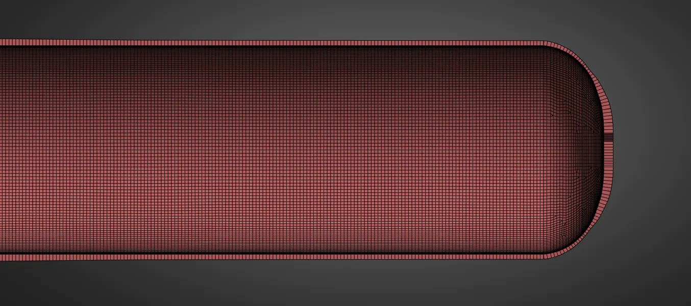
A high pressure Type-4 CNG composite cylinder required advanced structural evaluation under severe proof pressure testing. Filament wound composite vessels inherently exhibit variable thickness profiles featuring heavy fibre accumulation at the domes and localized ply terminations along the cylinder body. The objective was to build an accurate Finite Element Analysis (FEA) model that captures true laminate behaviour without over simplifying the composite architecture.
What was at risk
Standard FEA modelling techniques often rely on uniform ply assumptions or discrete, stepped thickness zones. When applied to complex filament wound geometries, these abrupt thickness transitions act as geometric discontinuities in shell element meshes. In preliminary model iterations, these steps generated severe artificial stress concentrations near the dome transitions, triggering false failure predictions and masking the vessel's true structural capacity.
Solution offered
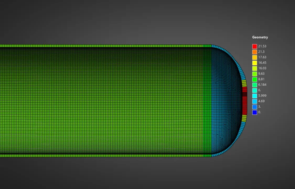
Our team engineered a specialized pre-processing methodology in Composite PrepPost to transition from stepped zones to a fully continuous, spatially varying composite layup. By integrating spatial interpolation functions with custom edge tapering rules, we mapped continuous thickness profiles and smooth ply drop-offs directly across the shell geometry. This eliminated artificial edge singularities, accurately captured balanced angle-ply architectures (+ / -), and established a reliable baseline for structural proof testing.
Challenges we overcame
Artificial Stress Singularities: Removed fictitious stress spikes caused by discrete, blocky thickness jumps in the FE shell mesh.
Complex Spatial Layups: Successfully mapped varying helical fiber accumulation and localized hoop ply drop-offs on a continuous surface geometry.
Solver & Spline Stability: Fine-tuned numerical interpolation fields in ACP Pre to ensure seamless mesh mapping without triggering element formulation instabilities.
How we executed
- 1
Geometric Boundary Segmentation: Divided the shell profile at key meridional reference points to establish precise spatial orientation sets.
- 2
Continuous Spatial Mapping: Configured spatial interpolation fields in composite modelling to dynamically scale ply thicknesses along the longitudinal tank axis.
- 3
Ply Drop-off & Taper Calibration: Applied edge-tapering rules and bounded selection sets to naturally ramp down internal hoop plies near the dome tangent lines.
- 4
Structural & Strain Validation: Transferred the continuous composite definition into ANSYS Mechanical to evaluate true fiber strain margins and failure criteria under full proof pressure.
Project outcome
Clean Stress Distribution: Completely eliminated false boundary stress spikes, producing smooth, physical stress contours across all dome to cylinder transitions.
Verified Margin of Safety: Confirmed that primary structural fibre strain levels operate well within safe allowable limits during high pressure proof testing.
Predictive Asset for Design: Provided the client with a robust, repeatable composite modelling framework suitable for future design variations and certification submissions.
Project gallery
Where this lives
Software used
Related solutions
Industries
At a glance
We apply the same rigour to every engagement
Let us show you what's possible for your product.