
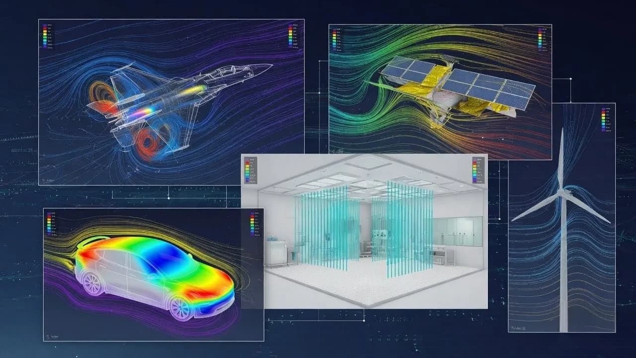
Computational Fluid Dynamics (CFD)
High-fidelity CFD simulation for aerodynamic, thermal, and multiphase flow problems using ANSYS Fluent and OpenFOAM.
What this solution covers
Pain points we address
Experimental testing of airflow and thermal performance is prohibitively expensive and time-consuming
Existing designs suffer from unknown pressure drops, flow maldistribution, or thermal hotspots
Inability to visualize internal flow paths makes root-cause analysis of performance issues guesswork
Competitive pressure to optimize energy efficiency and meet tightening regulatory standards
What we solve
External and internal aerodynamic flow analysis with drag, lift, and pressure distribution quantification
Conjugate heat transfer coupling fluid convection with solid conduction in heat exchangers and electronics
Multiphase flow modeling for liquid-gas separators, spray systems, and free-surface applications
Fan and blower performance prediction including system resistance curve matching
How we approach it
- 1
CAD preparation: clean and defeature geometry in SolidWorks, extract fluid volumes, define boundary zones
- 2
Meshing: generate hex-dominant mesh with boundary layer inflation using Fluent Meshing or snappyHexMesh
- 3
Physics setup: configure turbulence model (k-ω SST for wall-bounded, realizable k-ε for free-shear), heat transfer, and material properties
- 4
Solving: run steady-state or transient solution with convergence monitoring on residuals, mass/energy imbalance, and surface monitors
- 5
Validation and reporting: compare with available test data or empirical correlations, deliver flow visualization, pressure/temperature maps, and engineering summary
Deliverables
CFD methodology report documenting domain, mesh, physics setup, and convergence criteria
Flow visualization package: streamlines, velocity vectors, pressure contours, temperature maps
Quantitative results summary: pressure drops, heat transfer coefficients, drag/lift forces
Design optimization recommendations with comparative parametric study results
Solver case files (ANSYS Fluent .cas/.dat or OpenFOAM case directory) for client review
Expected outcomes
Quantified pressure drop and flow distribution enabling right-sized pump and fan selection
Thermal hotspot identification and elimination through design modification studies
Energy efficiency improvement of 10-30% through aerodynamic shape optimization
Reduced physical testing scope by pre-screening design variants computationally
Why Shirsh
We operate a dual-solver CFD practice — ANSYS Fluent for projects requiring commercial-grade validation traceability and advanced meshing, and OpenFOAM for engagements where HPC scalability, solver customization, or licensing economics are decisive. This flexibility lets us match the right tool to each project's technical and commercial requirements.
Related case studies
Aerodynamic Drag Optimization for Commercial HVAC Units
CFD-driven external aerodynamic study reducing fan power consumption by 18% on a commercial rooftop packaged air conditioning unit through systematic geometry modification.
ReadCFD Analysis of Wind Loading on Solar PV Arrays
ReadCFD Analysis of Basement Parking Ventilation
ReadCFD Analysis of Mixing Reactor
High-Fidelity CFD Simulation for Evaluating Mixing Performance, Flow Circulation, and Heat Transfer Using Dual Hydrofoil Agitators.
ReadCFD Analysis of Bench Top Fume Hood
High-Fidelity CFD Simulation for Airflow Distribution, Containment Performance, and Ventilation Design Validation
ReadRelated insights
Why Single-Axis Solar Trackers Need FEA, CFD, and Aeroelastic Analysis — Not Just IS 875
A single-axis solar tracker can clear every line of IS 875, pass its STAAD model, and still fail in a windstorm that never reached the code design speed. The reason is uncomfortable but simple: the code hands you a static pressure, and the structure that tore apart was responding to a dynamic, fluid-structure problem the code was never written to see. This is sharpest with single-axis trackers, which behave less like a stiff steel frame and more like a bridge deck on a torsional spring. Here is where IS 875 stops, where FEA and CFD pick up, and why "passes the code" and "survives the wind" are two different questions.
ReadWhy Fixed-Tilt Ground-Mount Solar Structures Fail
Fixed-tilt ground-mount is the structure everyone treats as solved. No moving parts, a straight load path from module to rail to post to ground, a static wind check, done. That reputation for simplicity is precisely why these structures fail — not from exotic physics, but from foundations pulled out of the soil, connections detailed for the wrong load direction, slender members that buckled under uplift, and corners that saw far more wind than a borrowed coefficient ever admitted. Walk the load path with a failed array in front of you and the causes are rarely mysterious. Here is how to read the damage, and the analysis chain that would have caught it on paper.
ReadWhy a Cleanroom Can Pass Certification and Still Contaminate Product
A particle count taken at a handful of certified sample points tells you the room is clean where you measured. It says nothing about the stagnant corner behind a filling line, the slow recirculating loop above a microscope, or the pocket of air near a return grille that holds onto contamination far longer than the air-change rate suggests. This is where CFD earns its place. By resolving the actual velocity field and tracking how particles move through it, simulation shows you the air a cleanroom forgets — the regions that pass paperwork but quietly drive your defect rate. With ISO 14644-5:2025 now asking facilities to justify their monitoring locations with airflow studies, that picture has gone from useful to expected.
ReadLeveraging OpenFOAM for Cost-Effective Industrial Fluid Analysis
How open-source CFD delivers commercial-grade accuracy for industrial flow and thermal simulation — without per-seat licensing constraints.
ReadHow to Check a Cold-Formed Solar Mounting Structure to IS 801: A Step-by-Step Guide
Most ground-mounted solar structures in India are made from cold-formed steel — thin steel sheet bent into channels and hat sections. Engineers find the wind load from IS 875 Part 3, then check the steel using IS 801. Two mistakes are very common. First, engineers use the full cross-section, but thin steel does not work that way — part of it buckles early, so the code makes you use only the "effective" part. Second, engineers check only the steady (static) load and skip the moving (dynamic) effects. This guide explains both problems in simple steps. It then checks the four main members of a solar structure — post, rafter, bracing, and a 1 mm hat purlin — with full numbers, so you can see exactly where the common shortcuts go wrong.
ReadFour Quiet Ways the IS 875 Wind Load Goes Wrong on a Solar Array
The wind-load calculation almost never fails an audit. It fails the structure. IS 875 (Part 3) is a sound loading code, and the arithmetic in most reports is right. What moves the answer is a handful of small choices in how the code gets applied, and on a light tilted array those small moves decide which members are under-built. Here is the chain done properly, and the four places it usually slips.
ReadWant to learn this?
We also offer ANSYS & SolidWorks training courses.
At a glance
Discuss your project with our engineers
Tell us about your simulation, validation or design challenge.