What Failure Reviews Teach About Where Structures Really Fail
Read a failure investigation and the first piece to let go is rarely the middle of a member. It is usually a connection, a small weld or a load path that changed after the calculations were done. I look at five public investigations and what they changed in the way I review FEA models.
When I read a failure investigation, I go to the part that says where the first piece let go. It is rarely the middle of a beam or the body of a shell, which are the parts we model most carefully. More often it is a connection, a weld put there for something else, or a load path that changed after the calculations were done.
I find that a useful corrective for simulation work, because our models are usually most confident about members and least honest about the places where load changes hands. Here is what I take from a few well-documented public investigations, and how it shapes the way I review an FEA model.
1. Connections fail before members do
The 1981 collapse of two suspended walkways in the Hyatt Regency hotel in Kansas City is the case most engineers know. The investigation by the US National Bureau of Standards (Building Science Series 143) traced it to insufficient load capacity of the box beam to hanger rod connections, with the first failure at the fourth floor walkway. The failure began at the connection, not in the rods.
Two findings from that report stay with me. Even the original design, with one continuous rod, would have given an ultimate capacity of approximately 60 percent of that expected under the Kansas City Building Code. And the change to two offset rods essentially doubled the load that the fourth floor box beam connections had to transfer.

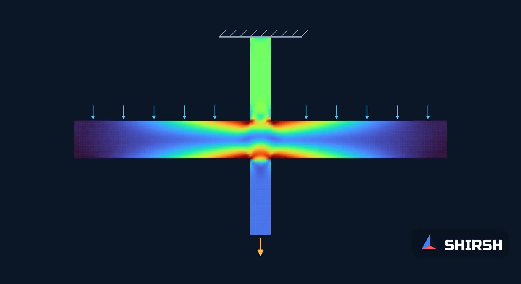
The hanger change in outline, after NBS Building Science Series 143. The rods looked much the same on the drawings. The upper connection went from carrying one walkway to carrying two.
The I-35W bridge in Minneapolis, which collapsed in August 2007, tells a similar story at a larger scale. The US National Transportation Safety Board found the probable cause in a design error in the gusset plates at the U10 nodes, which were about half the thickness of properly sized plates. It also named the practice of excluding gusset plates from load rating analysis as a contributing factor. Load ratings over the bridge's life looked at the members. The plates joining them were left out.
2. Small details carry large consequences
In March 1980 the Alexander L. Kielland accommodation platform capsized in the North Sea. The Norwegian Commission of Inquiry (NOU 1981:11) found that a fatigue fracture started in a small weld holding a flange plate for a hydrophone, in one of the braces that tied the support columns together. The weld belonged to a fitting, not to the structure, which is exactly the kind of detail a global design check passes over.
Ronan Point in London, in May 1968, is the other case I keep in mind. A gas explosion blew out load-bearing flank walls in a 22-storey large panel block, and a whole corner came down progressively. Each precast wall panel passed its weight to the panel below through its joints, so once one flank wall went, the panels above it had nothing left to stand on.
Neither failure would have been found by refining the mesh on the main members. In both, the governing location was a detail that the global design did not treat as structure.
3. The model can be the failure site
The concrete gravity base of the Sleipner A platform sank during a controlled ballasting test in Norway on 23 August 1991. The investigation summary from SINTEF attributes the loss to an inaccurate finite element approximation of the tricell walls, which underestimated the shear stresses by 47%, together with insufficient anchorage of the reinforcement in a critical zone. The wall failed at a depth of 65 m, and a later analysis of the same design predicted failure at 62 m.
I do not read Sleipner as a story about bad software. I read it as a reminder that a finite element result is itself an approximation, and that the place where it is least reliable, a junction of walls, was the place that governed. That is why I keep arguing for a mesh check at the governing location and for knowing whether a peak is real or an artefact before anyone designs to it.
4. Load paths change after the drawings
At the Hyatt, the hanger arrangement changed between design and fabrication. On the I-35W bridge, the NTSB pointed to substantial increases in weight from earlier modifications, and to construction equipment and aggregate staged near node U10 on the day. In both cases the structure was carrying loads along a path that differed from the one in the original calculation.
The codes have absorbed part of this. In the UK, Part A of the Building Regulations now requires that a building will not suffer collapse to an extent disproportionate to the cause, and EN 1991-1-7 sets out accidental actions and robustness measures such as tying. Our own steel code, IS 800:2007, gives connections their own section, and EN 1993-1-8 does the same for joints. None of these documents can check a change made on a shop drawing after the model was frozen, though.
5. What this changes in my FEA reviews
When I review a structural model now, I start at the joints rather than the members. I want to see how each connection was represented: bonded contact, rigid links, a beam element for a bolt, or a pinned idealisation. Each of those choices decides how load is shared, and each can hide a peak that a local model would show. If the global model ties a bracket to a plate along its full edge, I ask what the weld or bolt group actually looks like and whether it was checked separately.
I also ask for the load path to be described in words in the report: where the load enters, which parts it passes through, and where it leaves. If the analyst cannot write that down, the model has probably not been checked against it. Attachments, cut-outs and fittings added late get the same question. And when a drawing changes after analysis, the first thing I look for is whether any connection now carries more than it was checked for.
Where Shirsh fits
At Shirsh Technosolutions we carry out structural FEA and third-party design checks with ANSYS Mechanical, CalculiX and Code_Aster, with local models of connections, welds and bolted joints where the global model cannot resolve them. If you would like a second look at how your model treats its connections, please get in touch.
References: National Bureau of Standards, Investigation of the Kansas City Hyatt Regency Walkways Collapse, Building Science Series 143, 1982 (abstract and executive summary). National Transportation Safety Board, Collapse of I-35W Highway Bridge, Minneapolis, Minnesota, August 1, 2007, report HAR-08/03, and NTSB press release of 14 November 2008. Norwegian Commission of Inquiry, NOU 1981:11, Alexander L. Kielland accident. SINTEF summary of the Sleipner A gravity base structure failure, 1991. UK Building Regulations, Approved Document A, requirement A3 (disproportionate collapse). EN 1991-1-7, Accidental actions. EN 1993-1-8, Design of joints. IS 800:2007, General Construction in Steel, Section 10 (connections).
Related case studies

Want to Apply This to Your Product?
Our engineers can help you implement these techniques on your specific components and assemblies.
Get insights like this in your inbox
Engineering deep-dives, simulation tips, and industry analysis. No spam, unsubscribe any time.