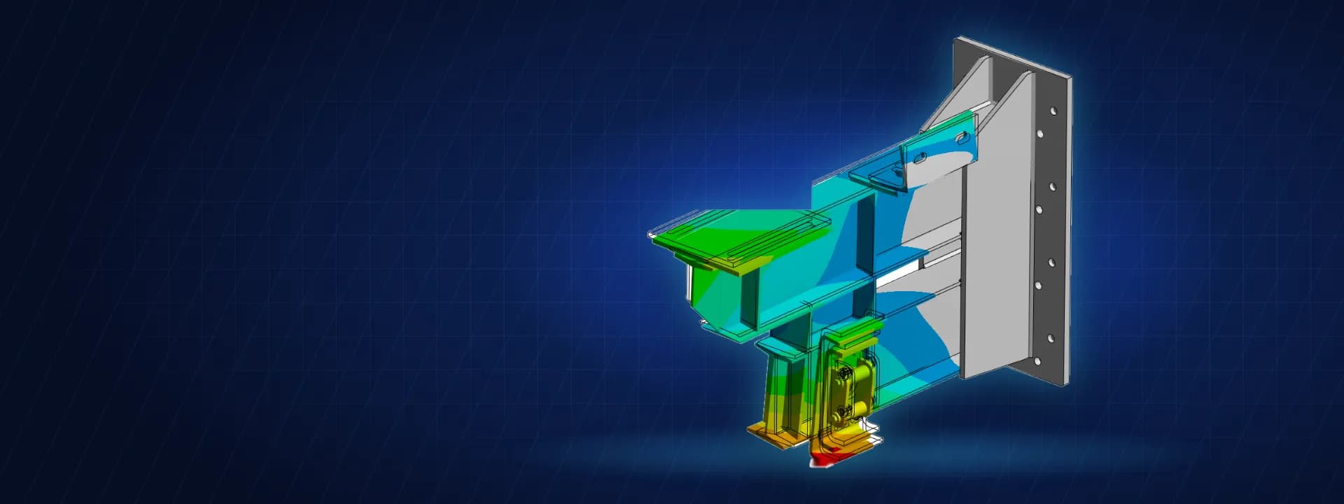
Structural FEA of a Level Locking Bracket for a Multilevel Parking System
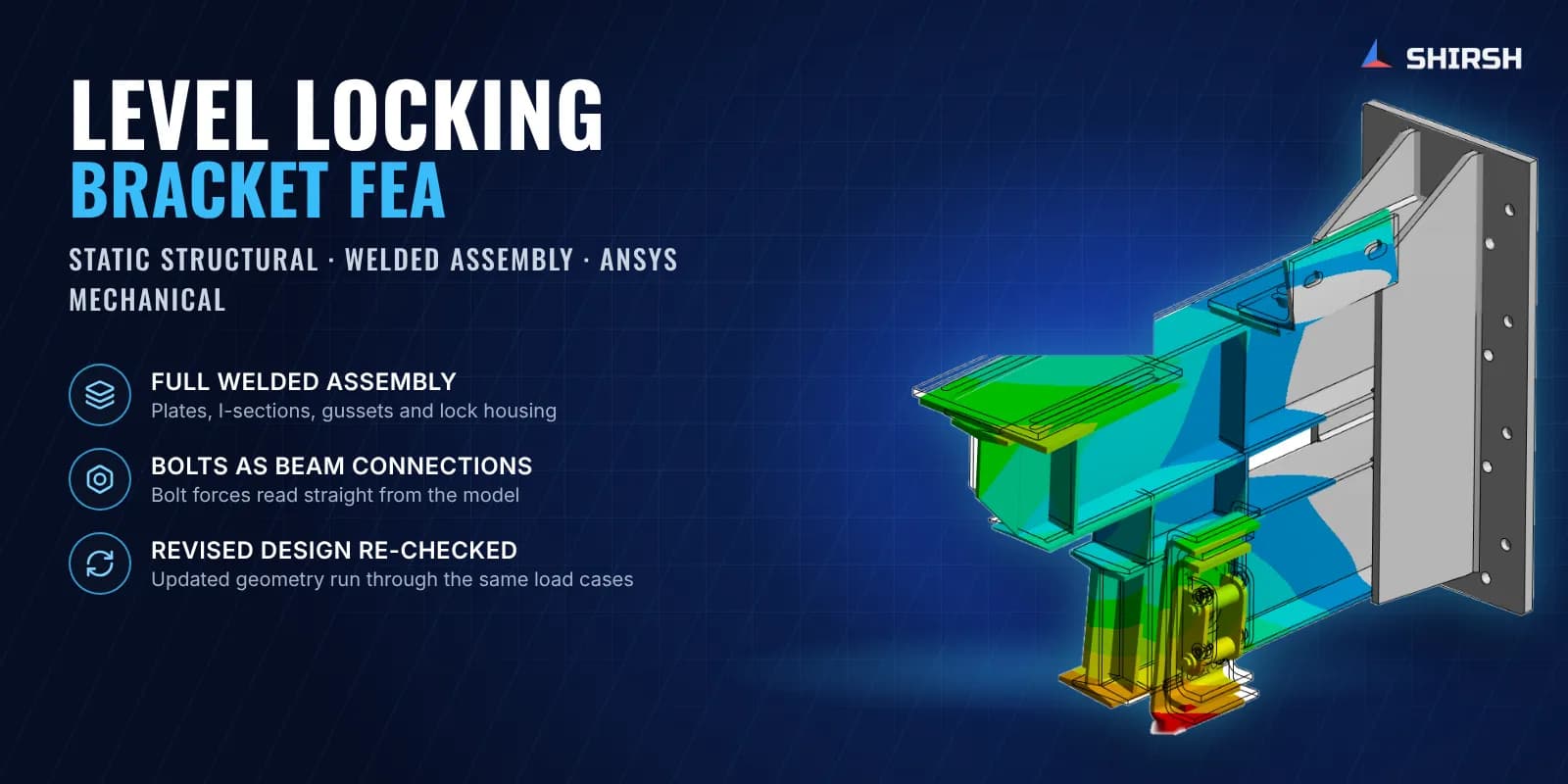
Static FEA of a welded level locking bracket for a multilevel car park, done to settle a load question that had put its production on hold.
Project brief
A maker of multilevel car parking systems had stopped production of a level locking bracket because of doubts over the loads it would carry in service. The bracket holds the parking pallet at each level, so it takes the weight of the parked car and also the side force when the lock engages.
Shirsh Technosolutions analysed the full welded bracket in ANSYS Mechanical. The client wanted a clear answer on whether the bracket could carry the new loads, where it was working hardest and what force each bolt would see, so that strengthening and fastener size could be decided before production restarted.
What was at risk
The bracket is a welded build-up of I-sections, gusset plates, tube sections and a lock housing, bolted to the main structure through a back plate. The plates are IS 2062 E350 and the tubular members IS 4923 YST 310, so the check had to respect two material grades.
Two load conditions had to be covered: the vertical load from the parked vehicle and the lateral load from the locking action on the pallet. Every load path ends in the welds and the bolts. The sharp re-entrant corner where the I-section meets the vertical gusset is also the kind of place where a linear model throws up stress peaks that are not real, and these had to be separated from the genuine stresses before anyone could judge the design.
Solution offered
We built a solid model of the complete assembly with the welds modelled as fillet bodies, so the load passes through them the way it does in the real part. Plates and sections were meshed with multizone hexahedral elements and the weld fillets with a finer tetrahedral mesh. Bonded contacts tied the welds to the parent plates.
The bolts were modelled as beam connections to ground at the actual hole positions. This holds the bracket the way the main structure does and gives the axial and shear force in each bolt straight from the solution.
Each load condition was solved on its own. We then reviewed deformation and equivalent stress over the whole assembly, zoomed into every hotspot and decided whether each peak was a true stress or a singularity at a sharp corner. The client revised the geometry during the job, and the revised design went through the same load cases.
Common questions
What is a stress singularity, and why is it set aside? At a perfectly sharp re-entrant corner the linear elastic stress keeps rising as the mesh is refined, so the peak depends on the mesh and not on the design. Such spots are judged by the stress a short distance away, or by a weld or hotspot method, rather than by the single peak value.
Why model bolts as beam connections? It keeps the model light and still reports axial and shear force at every bolt, which is exactly what the fastener check needs.
Challenges we overcame
Production on hold until the bracket was cleared for its service loads
Welded assembly of I-sections, gussets, tubes and a lock housing in two steel grades
Separating mesh-dependent singularity peaks at sharp corners from real stresses
Getting a usable force at every bolt for fastener sizing
Geometry revised by the client while the job was running
How we executed
- 1
Reviewed the CAD and prepared it for meshing, keeping the weld fillets as separate bodies
- 2
Meshed plates and sections with multizone hexahedra and the welds with finer tetrahedra
- 3
Tied the welds to the parent metal with bonded contacts
- 4
Modelled the bolts as beam connections to ground at the real hole positions
- 5
Solved the vertical vehicle load and the lateral locking load as separate cases
- 6
Reviewed deformation, equivalent stress and hotspots, and classed each peak as real or singular
- 7
Extracted axial and shear force at every bolt
- 8
Ran the revised geometry through the same load cases
Project outcome
Away from the singular corner at the I-section to gusset joint, stresses in the bracket stayed within the allowable limit for both load cases.
The singularity was identified and explained, so it did not drive an unnecessary redesign.
Bolt forces were reported for every connection, giving the client the input for fastener selection.
The client had an analysis basis for its decision on the bracket and its fasteners.
Project gallery
Where this lives
Software used
Related solutions
At a glance
We apply the same rigour to every engagement
Let us show you what's possible for your product.