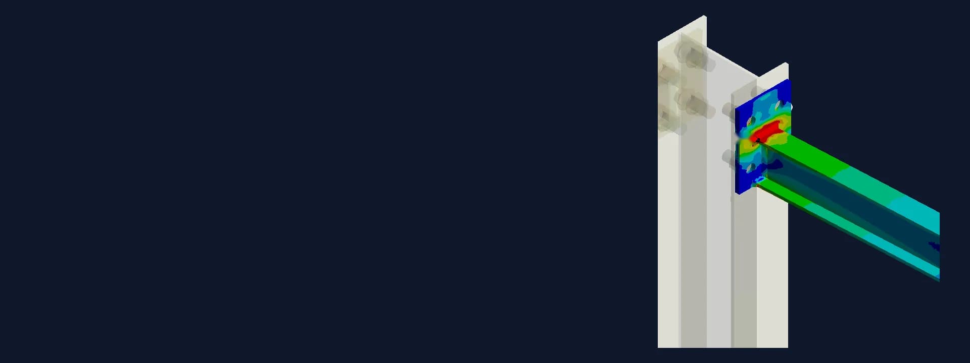
Cantilever Rack Arm Weld Joint FEA: Gusset Design to IS 800 and AISC ASD
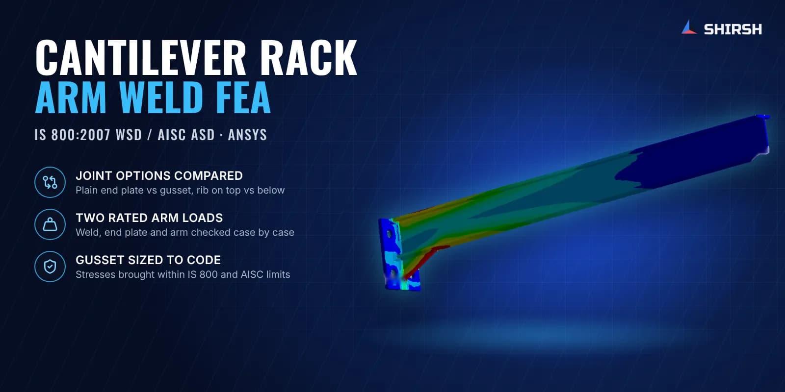
Cantilever rack arm FEA in ANSYS: weld joint, end plate and gusset options checked to IS 800:2007 WSD and AISC ASD for two rated arm loads.
Project brief
A storage rack manufacturer was building cantilever racks for long and bulky goods, the kind of rack where I-section arms stick out from a central column with nothing at the free end. Each arm is welded to an end plate, and the end plate is bolted to the column. The maker wanted to rate the arm for a heavier load and needed to know whether the welded joint at the root of the arm could take it.
Shirsh Technosolutions carried out cantilever rack arm FEA in ANSYS Mechanical. The study looked at the weld, the end plate and the arm itself, first without any stiffener and then with a gusset under the arm, and checked every case against the working stress design method of IS 800:2007 and AISC ASD.
What was at risk
In a cantilever rack the whole arm load comes back to one small area. The arm acts like a short beam fixed at the column, so the bending moment peaks right at the weld between the arm and its end plate. A fillet weld and a thin plate have to carry that moment as tension, compression and shear all at once, and the end plate also bends around its bolts. Hand calculations treat this joint as a simple connection, which says little about where stress actually piles up.
The manufacturer had a few direct questions:
would the existing arm-to-end-plate weld carry the rated load with no stiffener at all
if a stiffener was needed, should the rib or gusset go on top of the arm or below it
what gusset size would bring the weld, end plate and arm within the code limits at both the standard and the higher arm rating
Solution offered
Rib placement study first. Before the weld check, Shirsh compared the arm with no rib, with a rib on the upper side and with a rib on the lower side, looking at how much the arm tip deflects in each layout. The rib on the upper side gave the stiffest arm. The lower rib deflected noticeably more and was not recommended for stiffness.
Detailed joint model. For the weld study, a 3D model of the column, end plates, bolts, gusset and I-section arms was built from the client's drawings. Shell and solid elements were used with contact between bolted parts, the weld region was modelled as its own body, and the column base was fully fixed. Self-weight was applied from material density and the rated load was applied vertically on each arm.
Allowables from the material certificates. Allowable stresses for the end plate and gusset, the I-section and the weld metal were taken from the supplier test certificates using the working stress approach of IS 800:2007 and AISC ASD, with separate allowables for normal and shear stress.
Three cases, checked part by part. The joint was solved without a gusset at the standard rating, and with a gusset at the standard and the higher rating. For each case von Mises stress and the shear stress in all three planes were read at the weld, the end plate and the arm, and compared with the allowables.
A gusset that works at both ratings. The plain joint was well over the weld and end plate limits, so a gusset was clearly needed. When the client tried a smaller gusset, the model showed the gusset and its weld were still overstressed. A longer gusset was then sized, and its thickness was set so that the weld, end plate and arm stayed within the allowables at the higher rating too. The client got one gusset detail for both arm ratings.
Common questions
Why does a cantilever rack arm need a weld joint FEA? The arm is fixed only at the column, so the highest bending moment sits right at the arm-to-end-plate weld. FEA shows how that moment spreads through the weld, the plate and the bolts, which a simple connection calculation cannot show, and it tells you whether a gusset is needed.
Is a gusset better on top of or below a cantilever arm? It depends on what you are trying to control. In this study a rib on the upper side gave the lowest arm deflection, while a gusset below the arm was the practical choice to relieve the weld and end plate. Both were checked in the model before the detail was fixed.
Challenges we overcame
The full arm moment concentrated at one fillet weld and a bolted end plate
No stiffener on the original joint and a request to rate the arm for a heavier load
Choosing between a rib on top of the arm and a gusset below it
A first, smaller gusset that still left the gusset and its weld overstressed
One joint detail needed to cover two arm ratings
How we executed
- 1
Received the rack, column, arm and end plate drawings and the material test certificates from the client
- 2
Compared arm deflection with no rib, a top rib and a bottom rib
- 3
Built the 3D model of the column, end plates, bolts, gusset and I-section arms with a separate weld body
- 4
Set allowables for plates, sections and weld metal to IS 800:2007 WSD and AISC ASD
- 5
Solved the plain joint at the standard rating and checked von Mises and shear stress at the weld and end plate
- 6
Added a gusset below the arm, checked the client's first size and showed where it was still overstressed
- 7
Sized a longer, thicker gusset and checked it at both the standard and the higher rating
- 8
Issued the report with deformation and stress plots and a pass/fail summary for each case
Project outcome
The study showed the unstiffened arm joint was not adequate at the rated load.
A rib on the upper side was found to give the stiffest arm, and the bottom rib was not recommended for deflection.
With the final gusset below the arm, the weld, end plate and arm were within the IS 800 and AISC ASD limits at both arm ratings.
The client received a single, code-checked gusset detail for production.
Project gallery
Where this lives
Software used
Related solutions
Industries
At a glance
We apply the same rigour to every engagement
Let us show you what's possible for your product.