Stress Singularities in FEA: How to Tell a Real Peak from a Mesh Artefact
A red spot at a sharp corner that climbs every time you refine the mesh is usually a stress singularity, not a real stress. Using a simple L-bracket study run at five mesh sizes, this article shows how to recognise one, why the highest number in a model can end up at a support, and the methods that give a stress you can actually design with.
Read the full article below for the methodology, the data, and the engineering decisions behind it.
Every FEA engineer has seen it. The model solves, the contour plot comes up, and there is a small red spot at a sharp inside corner showing a stress well above yield. Refine the mesh and the number goes up. Refine again and it goes up again. The design was fine yesterday and now it looks like it is failing, even though nothing about the part has changed.
That red spot is very often a stress singularity. It is a property of the model, not of the steel, and treating it as a real stress leads to two kinds of bad decisions. One is redesigning a bracket that never needed it. The other, worse one is learning to ignore red spots in general, including the ones that are real. This article shows, with a small worked example, how to tell the two apart and what to report instead.
1. What a singularity is
Linear elastic theory has a known weakness. At a perfectly sharp re-entrant corner, a point load, a point support or the edge of a fully fixed face, the theoretical stress is infinite. For a 90 degree inside corner, the kind you get where two plates meet at right angles, the elastic solution near the corner grows roughly as r-0.46, where r is the distance from the corner. Halve the distance and the stress goes up by about 37 percent, all the way down to zero.
A finite element model cannot show infinity, so it shows whatever the mesh allows. Smaller elements sample the field closer to the corner and so report a higher number. This is why the peak never settles. The mesh is behaving correctly. The question being asked of it has no finite answer.
Real parts do not have infinitely sharp corners and steel does not stay elastic at infinite stress. The physical stress at the corner depends on the actual radius, the weld profile or the local yielding, none of which a sharp-cornered linear model contains.
2. A small test: the L-bracket
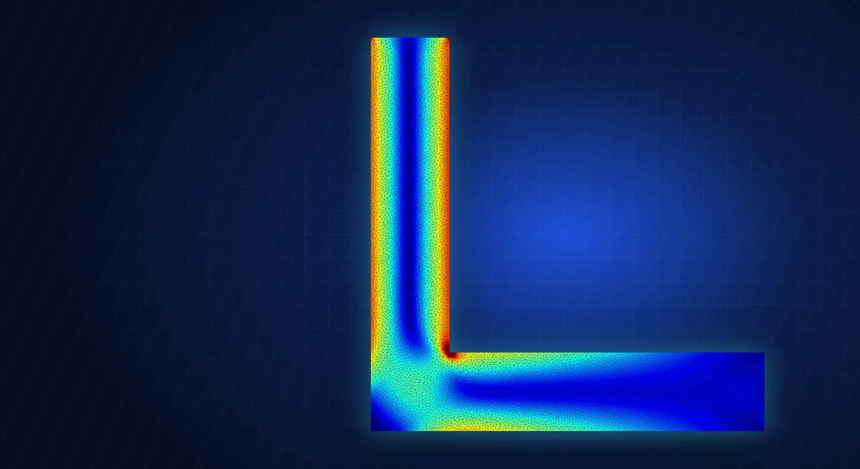
To make this concrete, we built a simple model. It is an L-shaped steel bracket with two arms 100 mm long and 20 mm wide, 10 mm thick, solved as a 2D plane-stress problem. The top edge of the vertical arm is fully fixed, as if welded to a wall, and a 1 kN downward load is applied at the free end of the horizontal arm. The inside corner where the arms meet is the point of interest.
We solved two versions. One has a perfectly sharp inside corner. The other has a 5 mm fillet at the same spot. Each was meshed at five element sizes, from about 4 mm down to about 0.25 mm, using quadratic triangles. Simple beam theory puts the nominal bending stress at the root of the horizontal arm at 120 MPa.

Sharp inside corner, fine mesh. The stress field is smooth everywhere except the corner itself, where it climbs without limit.
3. What the numbers show
The table below gives the highest von Mises stress found at the corner for each mesh, along with the stress at a point 5 mm from the corner.
Element size (mm) | Sharp corner, peak (MPa) | Sharp corner, 5 mm away (MPa) | 5 mm fillet, peak (MPa) |
|---|---|---|---|
4 | 315 | 65.3 | 238 |
2 | 402 | 64.2 | 238 |
1 | 612 | 64.5 | 238 |
0.5 | 779 | 64.6 | 238 |
0.25 | 887 | 64.7 | 240 |
Three things stand out.
The sharp-corner peak never converges. It almost triples between the coarsest and the finest mesh, and there is no sign of it levelling off. Any one of these numbers could be written into a report, and every one of them would be wrong in the same way.
A short distance away, the same model is perfectly well behaved. At 5 mm from the corner the stress hardly moves across a sixteenfold change in element size. The singularity is very local. Most of the model is giving good answers, and only the corner is misleading.
With the fillet, the peak converges at around 238 MPa. That is about twice the nominal bending stress at the root of the arm, and it is a real number. A designer can work with it.

Peak stress against element size. The sharp corner keeps rising as the mesh is refined, while the filleted corner and the stress at a distance stay flat.
4. The trap at the supports
One more result from the same study is worth showing. On the filleted model at the two finest meshes, the highest stress in the whole model was no longer at the fillet. It had moved to the corner of the fixed edge at the top of the vertical arm, where it read 240 MPa and then 258 MPa, while the fillet stayed at 238 to 240 MPa.
That support stress is also a singularity. A fully fixed edge stops the material from contracting sideways, and at the end of that edge the theory again gives an unbounded stress. In the sharp-corner runs it rose steadily from about 147 MPa to 285 MPa as the mesh was refined, without ever settling.
The lesson is simple. If you read only the maximum value reported for the model, a fine enough mesh will eventually point you at a boundary condition, not at the part. Always check where the peak is before you check what it is.

The 5 mm fillet. The peak sits on the fillet surface and stays the same as the mesh is refined.
5. Where singularities hide in real models
Sharp inside corners are the obvious case. In day-to-day consulting work we see them in a few other places just as often.
Weld toes and plate junctions modelled without any radius, which is most welded assemblies built from solids or shells.
Loads or supports applied at a single node, or on a very small face, such as a point mass, a remote point with a tiny scoping area, or a bolt load spread over one edge.
Fully fixed faces, especially at their edges and corners, where the real support has some flexibility.
The edge of a bonded contact region, where two parts are glued together in the model but would bear and separate in reality.
Shell-to-solid joints and beam-to-shell connections, where load is transferred through a line or a point.
None of these mean the model is useless. They mean that the stress right at that location has to be read differently.
6. What to do with a singular peak
The right method depends on what the result is for. These are the approaches we use.
Model the real geometry. If the stress at that corner matters, put in the actual radius from the drawing and mesh it properly. The peak will converge and you get a usable number, as the fillet case shows. If the drawing has no radius, ask the client what the shop actually produces.
Read the stress away from the singular point. For a static strength check, membrane and bending stress through the section are what decide failure. ASME Section VIII Division 2, Part 5 makes this formal: stresses are linearised along a stress classification line through the wall, and the peak component is kept out of the primary stress check. The same idea works for structural steel, where the stress in the plate a short distance from the junction is compared with the allowable.
Use a recognised method for welds. Weld toes are singular in a linear model by nature. Fatigue checks therefore use either a nominal stress with a classified detail category, or a hot-spot stress obtained by extrapolating surface stresses read at set distances from the toe, such as 0.4t and 1.0t in the IIW recommendations for a fine mesh. Reading the toe node directly is not one of the recognised methods.
Use a submodel. Where a detail genuinely matters, cut it out, apply the displacements from the global model at the cut boundary and mesh the detail finely with the real geometry. This keeps the global model light and gives a converged local answer.
Let the material yield where the code allows it. For ductile materials under static load, a local peak above yield redistributes. An elastic-plastic analysis, where the code permits it, shows whether that redistribution is harmless or whether a real plastic mechanism forms.
Put supports where they belong. If the peak sits at a fixed face, ask whether that face is really rigid. Modelling the bolts, the base plate or the adjoining structure, or simply moving the support further away from the area of interest, usually removes the false hotspot. By Saint-Venant's principle, it will not change the stress in the region you care about.
7. A reviewer's checklist
When we review FEA reports prepared by others, these are the questions we ask about any peak stress.
What you see | Likely cause | What to ask for |
|---|---|---|
Peak at a sharp inside corner | Geometric singularity | Real radius modelled, or stress read at a defined distance or linearised |
Peak rises each time the mesh is refined | Singularity, not a converged stress | A mesh study at the peak location, not just a global one |
Peak at a fixed support or load point | Boundary condition artefact | Realistic support stiffness, or the peak excluded with a reason |
Peak at a weld toe used for fatigue | Toe singularity | Hot-spot extrapolation or nominal stress method, stated clearly |
Peak at the edge of bonded contact | Contact modelling choice | Frictional or separating contact where the parts can really separate |
Where Shirsh fits
Most of the FEA disputes we are asked to settle come down to a single red spot and a disagreement about what it means. Telling a singularity from a real stress concentration takes a mesh study at the right place, a clear method for reading the stress and a code basis for comparing it with the allowable. When those three are in the report, the argument usually ends quickly.
Shirsh TechnoSolutions provides FEA and CFD consultancy, design-by-analysis to ASME and third-party review of simulation reports. If you have a result you are not sure about, or a report that needs to stand up to a reviewer, please get in touch.
Click to view full size
Related case studies

Want to Apply This to Your Product?
Our engineers can help you implement these techniques on your specific components and assemblies.
Get insights like this in your inbox
Engineering deep-dives, simulation tips, and industry analysis. No spam, unsubscribe any time.