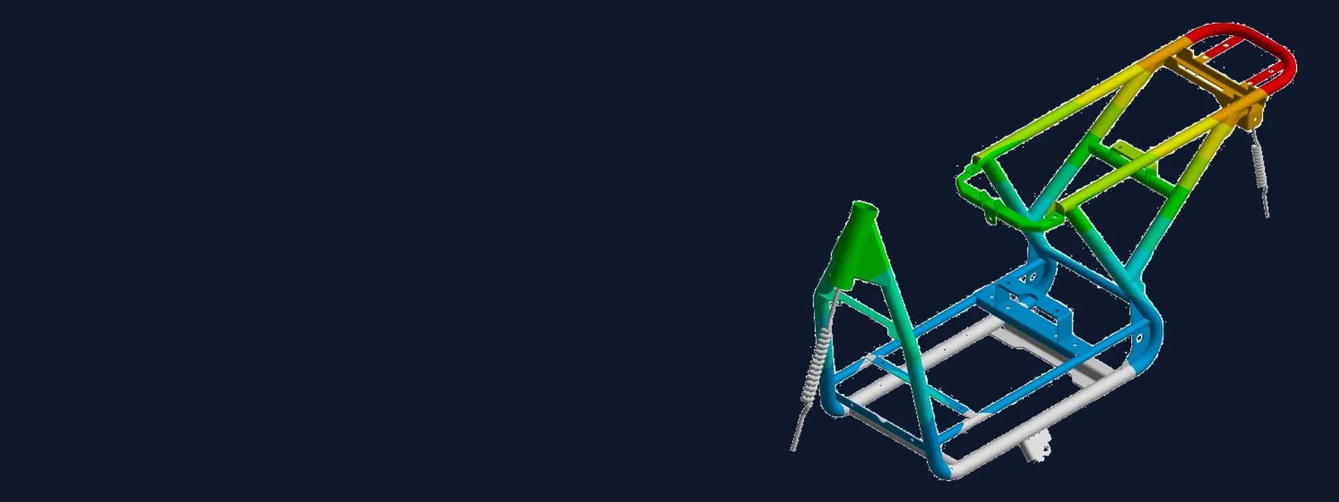
Electric Scooter Chassis and Swingarm FEA: Braking, Cornering and Fatigue Checks
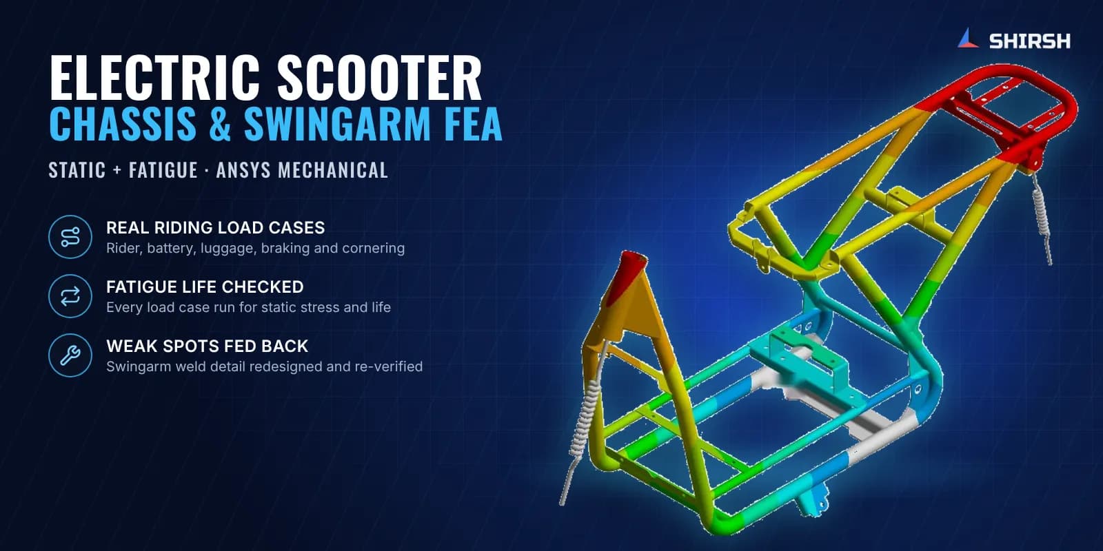
Electric scooter chassis and swingarm FEA in ANSYS: rider, battery and luggage loads, braking and cornering cases, and fatigue life checks.
Project brief
An electric two-wheeler maker in India was finalising the tubular chassis and swingarm of a new electric scooter. Before committing to tooling and prototypes, their R&D team wanted to know how both parts would hold up on the road, under the loads a loaded scooter actually sees when it brakes hard or leans into a corner.
Shirsh Technosolutions carried out an electric scooter chassis and swingarm FEA in ANSYS Mechanical. We checked static stress and fatigue life for each riding load case, flagged the zones that would not last, and verified a weld detail change on the swingarm before the design moved on.
What was at risk
A scooter frame is a welded tube structure carrying a rider, a pillion or payload, a heavy battery pack and often luggage on the rear rack. The loads move around. Under braking the mass pushes forward, in a corner it swings sideways, and in real riding both happen together.
Hand calculations work for a single tube. They do not tell you what happens at a gusset, a weld toe or a bracket where three tubes meet, and those are exactly the places where frames crack in service. Fatigue matters as much as peak stress here, because every pothole and every braking event adds another cycle.
The swingarm had its own concern. It carries the rear wheel and hangs on the suspension spring, so its weld joints see repeated bending every time the suspension moves.
The client needed:
the stress and fatigue picture for the chassis and the swingarm under realistic riding loads
the locations that would not survive, with a practical direction for each
a quick turnaround, so findings could go back into the CAD while the design was still open
Solution offered
Model and inputs. We took the client's 3D CAD of the chassis assembly and the swingarm and prepared both for meshing in ANSYS Mechanical. Material properties for the tubes and plates were taken from the client and confirmed by their team, along with the pipe test certificates. Front fork and rear spring stiffness came from the client's drawings, so the suspension was represented as springs instead of rigid supports.
Loads that match the vehicle. The rider and payload mass was applied on the seat rails, the battery mass at its actual mounting location, and extra luggage on the rear rack. These masses set up the dead load case. Inertial forces were then added for three riding cases: braking, cornering, and cornering with braking together.
Static and fatigue in one pass. For each load case we looked at total deformation, equivalent (von Mises) stress and fatigue life, using the ANSYS fatigue tool on the same model. This shows where the stress peaks and, just as useful, which joints would run out of life first under repeated loading.
Swingarm: a weld detail fixed and re-checked. The first swingarm run showed failure at the weld zone where the plate was welded only at a slot. We reported this to the client with the regions marked, and the detail was changed so that the complete edge is welded to the plate. The modified swingarm was re-run in all four load cases and came out safe in braking, cornering and the combined case, with fatigue life comfortably inside the analysis limit.
Chassis: clear feedback for the next revision. The chassis came through the braking case safely. In the cornering and combined cornering plus braking cases, stresses at a few tube joints were above the safe limit and fatigue life dropped sharply at the same spots. These zones were shown with close-up plots so the client's designers could see exactly where to add material or change the joint, and the chassis was taken up for modification on their side.
Common questions
What load cases are used in an electric scooter chassis FEA? Start with the static masses: rider and payload on the seat, battery at its mounting and luggage on the rack. Then add inertial loads for braking, cornering and both together, since the combined case is often the one that governs at the tube joints.
Why run fatigue as well as static stress on a two-wheeler frame? A frame can pass a one-off peak load and still crack after months of potholes and braking. A fatigue life check on the same model shows which welds and joints will fail first under repeated loading, so they can be fixed before prototypes are built.
Challenges we overcame
Welded tubular frame where stress collects at tube joints, gussets and brackets
Loads that shift with braking and cornering, and combine in real riding
Suspension stiffness represented as springs instead of rigid supports
Fatigue life needed alongside peak stress for every load case
A swingarm weld detail that failed in the first run and had to be re-verified after the change
How we executed
- 1
Prepared the client's 3D CAD of the chassis and swingarm for meshing in ANSYS Mechanical
- 2
Confirmed material properties with the client and used their pipe test certificates
- 3
Modelled front fork and rear spring stiffness from the client's drawings
- 4
Applied rider and payload, battery and luggage masses at their real locations
- 5
Added inertial loads for braking, cornering, and cornering with braking
- 6
Checked total deformation, equivalent stress and fatigue life for each load case
- 7
Reported the failing swingarm weld zone and verified the full edge weld change in all cases
- 8
Marked the chassis joints above the safe limit in cornering for the client's next design revision
Project outcome
The modified swingarm, with a full edge weld in place of the slot weld, was found safe in braking, cornering and combined braking plus cornering.
The chassis was confirmed safe in braking, and the joints that were overstressed in cornering were located precisely for redesign.
Weak spots were caught in the model before tooling and prototypes, while the design was still open.
The client received FEA reports for both parts with deformation, stress and fatigue plots for every load case.
Project gallery
Where this lives
Software used
Related solutions
Industries
Related insights
What Failure Reviews Teach About Where Structures Really Fail
Read a failure investigation and the first piece to let go is rarely the middle of a member. It is usually a connection, a small weld or a load path that changed after the calculations were done. I look at five public investigations and what they changed in the way I review FEA models.
ReadStress Singularities in FEA: How to Tell a Real Peak from a Mesh Artefact
A red spot at a sharp corner that climbs every time you refine the mesh is usually a stress singularity, not a real stress. Using a simple L-bracket study run at five mesh sizes, this article shows how to recognise one, why the highest number in a model can end up at a support, and the methods that give a stress you can actually design with.
ReadAt a glance
We apply the same rigour to every engagement
Let us show you what's possible for your product.