
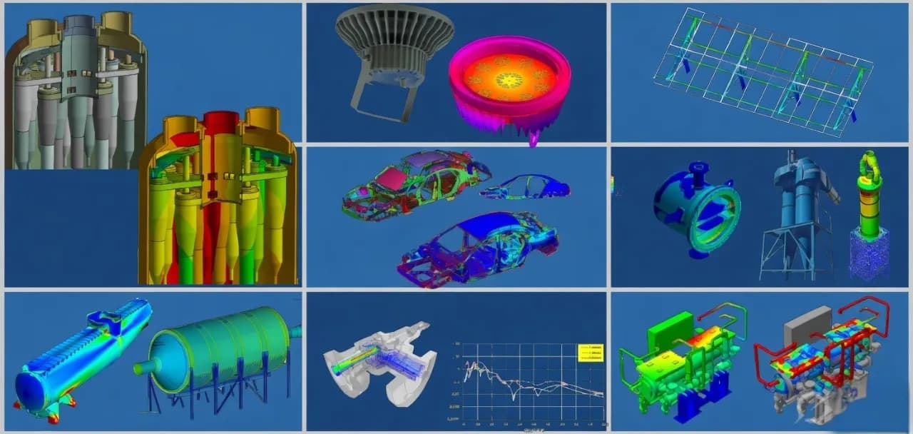
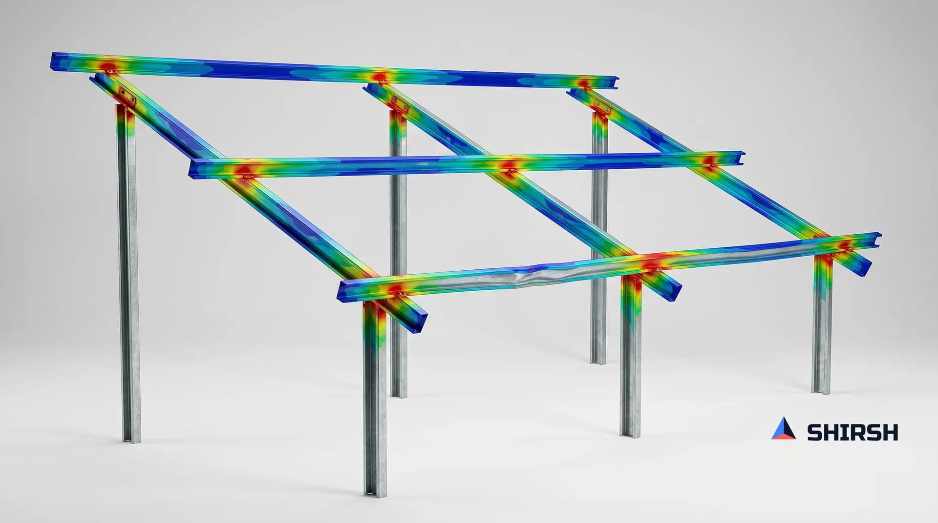
Structural FEA Analysis
Comprehensive finite element analysis services for structural integrity, fatigue life, and design optimization of industrial components and assemblies.
What this solution covers
Pain points we address
Physical prototypes fail during testing, causing project delays and cost overruns
Lack of in-house FEA expertise to validate designs against customer specifications
Uncertainty about fatigue life and long-term structural reliability under service loads
Designs are over-engineered due to insufficient understanding of actual stress distributions
What we solve
Structural adequacy assessment against applicable design codes (ASME, EN, IS)
Fatigue life prediction under constant and variable-amplitude loading
Nonlinear contact, large deformation, and material plasticity analysis
Dynamic response evaluation — modal, harmonic, random vibration, and seismic
Our approach, step by step
Deliverables
- FEA methodology document with assumptions and boundary condition rationale
- Detailed results report with stress/deformation contour plots and safety factor mapping
- Fatigue life report with damage fractions and critical location identification
- Design improvement recommendations with supporting parametric study data
- ANSYS Mechanical project files for client internal review and future reanalysis
Expected outcomes
Reduction in physical prototyping iterations by 40-60% through virtual testing
Design sign-off confidence backed by code-compliant FEA evidence
Weight reduction of 15-25% through stress-driven topology and parametric optimization
Accelerated development timelines by identifying failure modes early in the design cycle
Why Shirsh
Our engineers bring deep domain expertise in structural mechanics, material behavior, and industry code compliance. We don't just run simulations — we interpret results in the context of manufacturing feasibility, code requirements, and operational reality, delivering actionable engineering recommendations rather than raw contour plots.
Related insights


We also offer ANSYS & SolidWorks training courses
Ready to Solve This Challenge?
Tell us about your engineering problem — our team will propose a strategy tailored to your requirements.