
Roof Safety Lifeline FEA: Fall-Arrest and Static Strength Check on Metal Sheet Roofs
Roof safety lifeline FEA in ANSYS: fall-arrest and static strength checks of posts, anchors, rope grips and roof sheet to IS 3521 Part 8 / ISO 16024.
Project brief
A rooftop solar EPC company needed proof that its horizontal safety lifeline would hold a worker who slips on a metal sheet roof. The system is a stainless steel wire rope running between end, corner and intermediate posts, each post bolted to an anchor plate that is riveted to the roof sheet. The same kit had to work on trapezoidal, Kliplock, standing seam and aluminium sheet roofs, and the client wanted a longer span between posts than its first design.
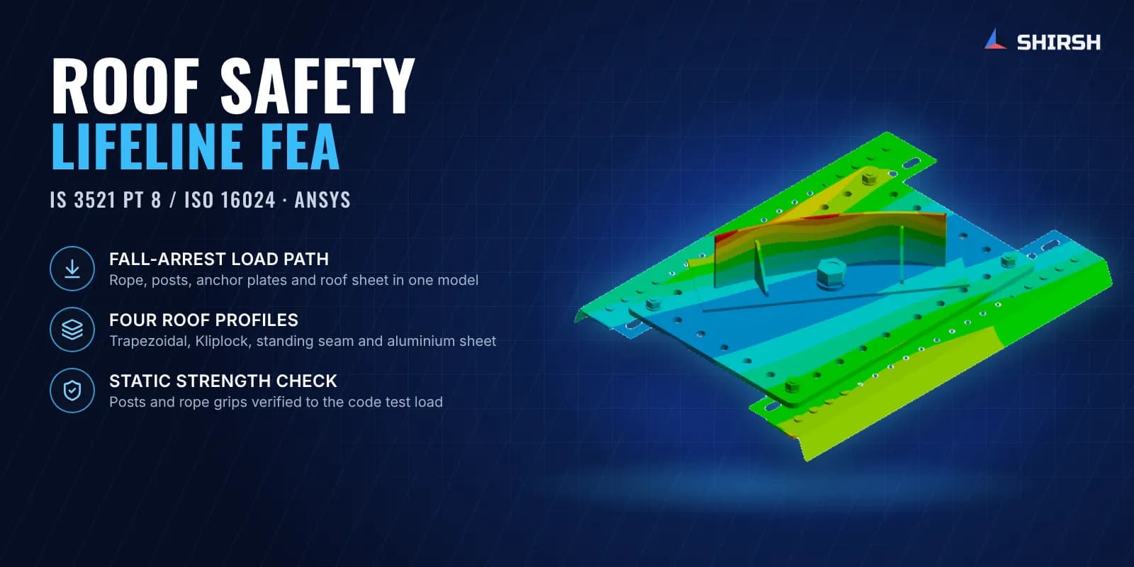
Shirsh Technosolutions carried out roof safety lifeline FEA in ANSYS Mechanical for each roof type. The rope, the posts and the roof sheet were checked under the user's static load and under a fall-arrest load, and later under the static strength test load of IS 3521 (Part 8) / ISO 16024, with a separate check of the wire rope grips at the rope ends.
What was at risk
A lifeline only gets tested for real when somebody falls. At that moment the rope swings into a sag, the pull at the posts goes up sharply, and the whole load ends up in a thin roof sheet through a handful of rivets. The posts are small parts with eye bolts, brackets and gussets, so stress tends to collect at the bolt threads, the rope junction at the corner and the welds at the base. Physical drop tests on every roof profile and post layout would take a lot of time and material.
The client and its design consultant wanted clear answers on a few points:
whether the rope, end posts, corner post and intermediate posts stay within yield under the design load and the fall-arrest case
how much of the force reaches the roof sheet, and the thinnest sheet the anchor plate could safely be fixed to
whether stretching the post spacing would push any part beyond its limit
whether the posts meet the static strength requirement of the lifeline code, and whether the rope end grips will hold without slipping
Solution offered
Two linked models. The work was split into a rope assembly model and a roof assembly model. The rope assembly (wire rope, posts, eye bolts, shock absorber, tensioner and brackets) was solved first, and its support reactions at each anchor plate were carried into the roof assembly model of anchor plate, rivets and roof sheet. Gravity was applied at the roof tilt so that self-weight acted the way it does on site.
Static and fall-arrest load cases. The static case covered self-weight plus the user's working load. For the fall-arrest case the user's load was multiplied by a dynamic amplification factor taken from published work on multi-degree-of-freedom systems, so the posts and roof saw the peak pull of a fall. Second-order solid and shell elements were used, mesh error was kept within normal FEA limits, and von Mises stress was compared with the yield strength of each stainless steel, structural steel and aluminium part.
Roof sheet and span study. The roof assembly was re-run for different sheet thicknesses to find the minimum sheet the lifeline anchor can be fixed to, and the rope layout was re-analysed for the longer post spacing the client asked for. The reaction forces at each anchor point were tabulated for the client's own connection design.
Static strength check to the code. In a later round each post type (end post with and without shock absorber, corner post and intermediate post) was loaded with the static strength test load of IS 3521 (Part 8) / ISO 16024 in a nonlinear static analysis. An appendix modelled the wire rope grips (designed to IS 2361) at the rope termination, worked out the clamping force from the bolt tightening, and showed that the friction it develops is more than the rope pull, so the rope will not slip.
Local peaks, read with care. Peak stress above yield showed up only in very small areas at bolt threads, cotter pins and the rope junction, the kind of local peak a bonded FEA model gives at contact points. These were reported separately from the general stress level and the components carrying them were flagged to the client. The reports also state that the lifeline is for one-time use and must be replaced after it has arrested a fall.
Common questions
How is a roof safety lifeline checked with FEA? The rope and posts are modelled together and loaded with the user's weight, then with an amplified fall-arrest load and the static strength test load from the lifeline code. The reactions at each anchor are then applied to a model of the anchor plate and roof sheet, so the check covers everything from the rope down to the roof.
Why does a lifeline FEA include the roof sheet? On a metal roof the weakest link is often the thin sheet and the rivets that hold the anchor plate, not the steel post. Modelling the sheet shows how the load spreads, and it tells the installer the minimum sheet the anchor can be fixed to.
Challenges we overcame
A fall-arrest event that loads the posts and roof far more than the user's static weight
Load path from a flexible wire rope down to a thin roof sheet fixed only with rivets
One lifeline kit to be proven on trapezoidal, Kliplock, standing seam and aluminium sheet roofs
A longer post spacing requested by the client after the first design
Local stress peaks at bolts, pins and rope junctions that had to be read correctly and flagged
How we executed
- 1
Received the lifeline CAD, drawings and roof sheet details from the client
- 2
Built the rope assembly model with end, corner and intermediate posts, shock absorber and tensioner
- 3
Applied self-weight at the roof tilt with the static working load and the amplified fall-arrest load
- 4
Transferred the post reactions to an anchor plate and roof sheet model and checked the sheet
- 5
Ran a sheet thickness study and re-analysed the layout for the longer post spacing
- 6
Checked each post type under the static strength test load of IS 3521 (Part 8) / ISO 16024
- 7
Modelled the wire rope grips at the rope ends and confirmed they resist slip
- 8
Issued reports with stress summaries, anchor reaction tables and flagged components for each roof type
Project outcome
The lifeline was checked from the rope down to the roof sheet for static, fall-arrest and code static strength loads.
General stresses in the rope, posts, anchor plates and roof sheet were within yield, with local peaks at bolts and pins reported and flagged.
The client got a minimum roof sheet thickness and anchor reaction tables for each roof type.
The rope end grips were shown to hold the rope without slipping, and the design was confirmed for one-time use after a fall.
Project gallery
Where this lives
Software used
Related solutions
Industries
At a glance
We apply the same rigour to every engagement
Let us show you what's possible for your product.