
Pressure Equipment Design-by-Analysis to ASME VIII Div 2
FEA-based qualification of pressure vessels, internals, nozzles, lugs and valve bodies to ASME VIII Division 2 Part 5, written for drawing approval and third-party review.
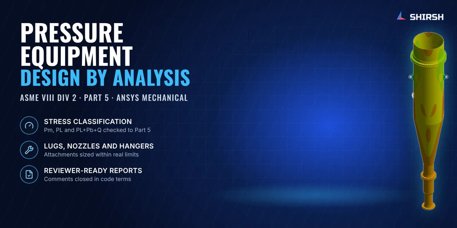
What this solution covers
When a vessel, an internal or an attachment falls outside the design-by-rule formulas, ASME Section VIII Division 2 Part 5 allows it to be qualified by analysis. Shirsh Technosolutions carries out that analysis in ANSYS Mechanical for fabricators, EPC contractors and valve makers, and writes it up so the reviewer can follow every check.
Typical jobs are cyclones and internals hung from hangers, nozzles with external loads, lifting and support lugs, skirts and saddles, and valve or fitting bodies under hydrotest. We stay with the job through review comments and design changes until the drawing is approved.
Pain points we address
Geometry or loading outside the design-by-rule formulas of the code
EPC or third-party reviewers rejecting peak von Mises plots as evidence
Drawing approval held up by comments on stress classification
Hangers, lugs and nozzles that are hard to size by hand within space limits
Hydrotest or upset cases that govern but were never part of the original calculation
What we solve
Elastic stress analysis to ASME VIII Div 2 Part 5 with linearisation and Pm, PL and PL+Pb+Q checks
Nozzle and attachment checks under external piping and equipment loads
Lifting lugs, trunnions, hangers, skirts and saddles for fabrication, erection and operation
Combined thermal and pressure cases with temperature-dependent allowables from ASME Section II Part D
Valve, fitting and connector bodies under design pressure and hydrotest
Fatigue screening where the service is cyclic
How we approach it
- 1
Review drawings, design data, code edition and the reviewer's expectations before modelling
- 2
Build the model from fabrication drawings with corrosion and erosion allowances removed
- 3
Mesh with second-order elements and enough layers through the wall to resolve bending, with a convergence check
- 4
Run thermal and structural cases with material data from ASME Section II Part D
- 5
Linearise at critical sections, classify each stress and check it against its Part 5 limit
- 6
Compare design options when a part fails, within fabrication and installation constraints
- 7
Issue a report written for the reviewer and close out comments to approval
Deliverables
Design-by-analysis report with load cases, linearisation paths and code checks
Stress classification tables for every critical section
Recommended design changes with the checks behind them
Written responses to reviewer comments
ANSYS Mechanical files on request
Expected outcomes
An analysis package the EPC or third-party inspector can approve
Stresses classified and checked the way Part 5 requires, so review comments close faster
Failing parts fixed with changes that still suit fabrication and installation
Fewer surprises at hydrotest and commissioning
Why Shirsh
Our engineers have done design-by-analysis for process, power and oil and gas equipment for over two decades. We linearise and classify stresses the way Part 5 asks, report each one against its proper limit and answer reviewer comments in the same terms. That last step is usually where approval time is lost, and it is where we spend the most care.
Where this lives
Industries served
Software used
Want to learn this?
We also offer ANSYS & SolidWorks training courses.
At a glance
Discuss your project with our engineers
Tell us about your simulation, validation or design challenge.