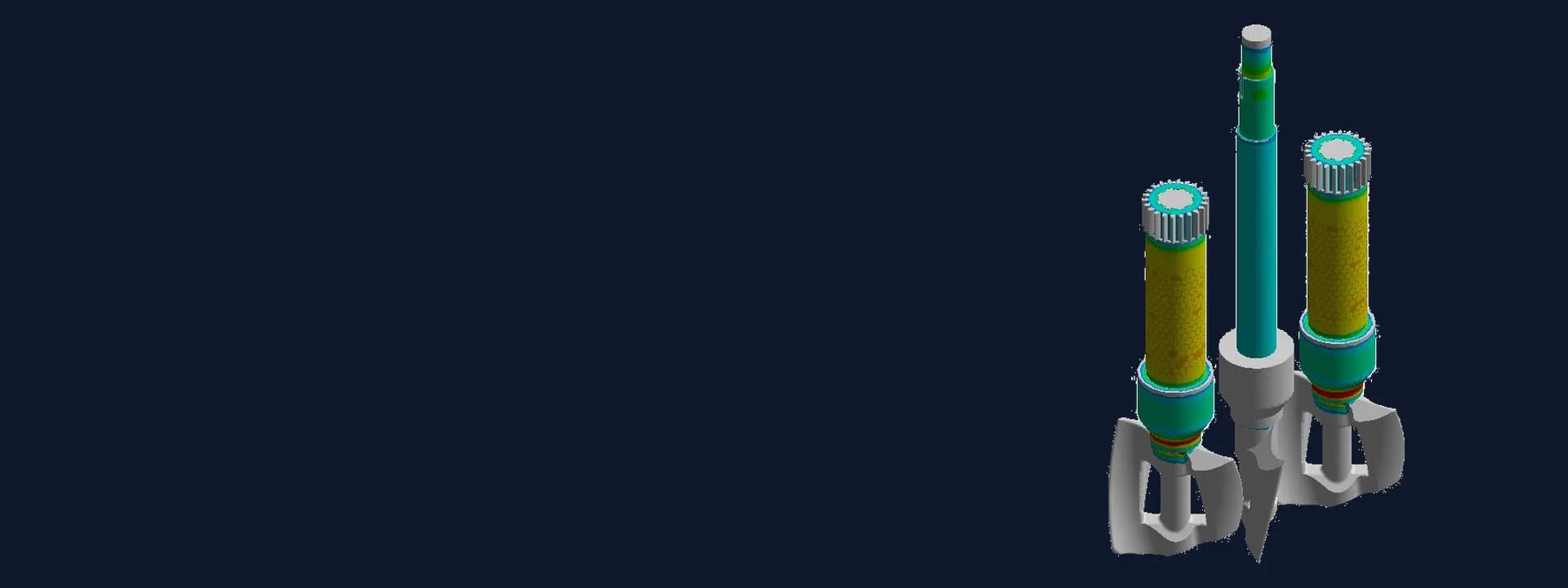
Planetary Mixer FEA: Blade, Shaft and Gear Strength from CFD Mixing Loads
Planetary mixer FEA in ANSYS with blade torques from CFD of a viscous mix, iterated with the maker until blades, shafts and gears met allowables.
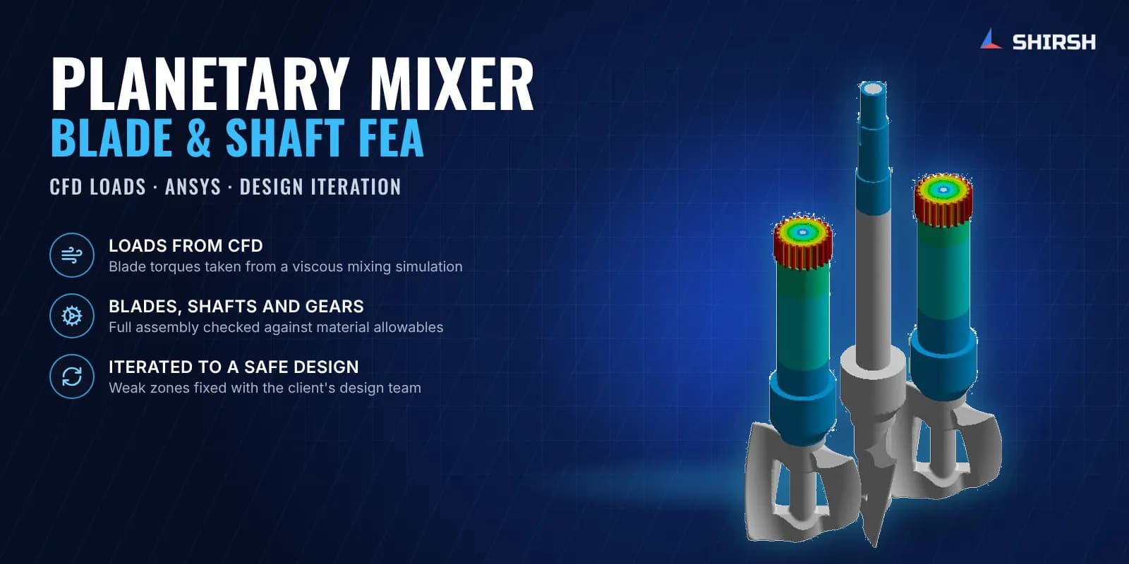
Project brief
A process equipment manufacturer was developing a double planetary mixer for a very thick, sticky material. The machine has a centre blade and two side blades that turn on their own axes while the planetary plate carries them around the bowl, all driven through one gear train. Nobody had a reliable number for the torque the blades would see in such a viscous mix, and the shafts, blade roots and gears had been sized on an estimate.
Shirsh Technosolutions worked out the real loads first, with a CFD simulation of the blades moving through the material, and then used those loads in a planetary mixer FEA in ANSYS Mechanical. Over several rounds with the maker's design team the weak zones were found, the design was changed, and the final blade and shaft assembly was checked against the allowable stress of each material.
What was at risk
In a planetary mixer the drive torque is set by the material, not by the motor catalogue. With a very viscous product the resistance on each blade is large, and it acts both about the blade's own axis and about the centre of the planetary motion. If the torque is guessed low, the shafts and the joint between blade and shaft are the first parts to give trouble.
The maker needed answers to a few practical questions before it could build the machine:
what torque the centre and side blades really carry in the actual material
whether the shafts, blade roots and gears could take that torque with a sensible margin
where exactly the design was weak, and what to change so the margin improved
the force on the shear pin in the gear drive, for sizing that pin
Solution offered
Loads from CFD instead of an estimate. The mixing chamber and blades were simulated in CFD with the viscous material, and the reaction moments on the centre blade and side blades were read from the solution. These came out much higher than the torque the client had first estimated, so the CFD values were agreed with the client and carried into the structural work. Torques at the motor, the eccentric gear and the blades were later reported in a consistent set of units for the maker's drive selection.
Assembly model and mesh. The blade assembly CAD was cleaned of fasteners, small holes and cosmetic chamfers, then meshed with second-order solid elements (hexahedral and tetrahedral) and shell elements where suitable. Element quality, aspect ratio, Jacobian ratio and skewness were checked before solving. Stainless steel and structural steel parts were assigned their own properties and allowables.
Supports and loads that match the machine. Cylindrical supports at the bearing seats left each shaft free to rotate while holding it radially and axially, and fixed supports held the gear end. The CFD moments were applied to each blade about its own axis, and the side-blade moments were also applied about the central axis to represent the planetary motion.
Iterating with the design team. The first rounds showed stress above yield at a few local regions and high shear at the blade-to-shaft joint. Shirsh reported the hot spots with stress and safety-factor plots, marked areas below the target factor, and suggested changes such as larger shafts, fillets at the blade roots and changes to the blade. The maker revised its CAD after each review and the model was re-run, until the final assembly was within the allowable stress everywhere.
Shear pin check. Using the peak moment from the analysis and the gear geometry, the shear force on the drive pin was calculated so the maker could size the pin.
Common questions
Why use CFD to find the load for a mixer FEA? In a viscous mix the torque on each blade depends on the material, the blade shape and the speeds, and simple estimates can be far off. A CFD run of the blades in the actual material gives the reaction moments directly, so the structural check starts from a realistic load.
What does design iteration with FEA look like for mixer blades? Each round shows where stress or the safety factor misses the target. The designer changes shaft size, fillets or blade shape at those spots, and the updated model is solved again, until every part meets its allowable before metal is cut.
Challenges we overcame
No reliable torque figure for blades running in a very viscous material
Moments acting about each blade axis and about the planetary centre at the same time
Local overstress and high shear at the joint between blade and shaft in the early designs
Several design revisions from the client, each needing a fresh model and solve
A drive shear pin that had to be sized from the analysis loads
How we executed
- 1
Received the mixer CAD, drawings, speed ratios and material data from the client
- 2
Simulated the blades in the viscous material with CFD and extracted the blade reaction moments
- 3
Agreed the CFD-based torques with the client in place of the initial estimate
- 4
Cleaned the assembly geometry and built a second-order mesh, checking mesh quality metrics
- 5
Applied bearing supports and the CFD moments about the blade and planetary axes
- 6
Reported stress, deformation and safety-factor plots and marked the weak zones
- 7
Suggested design changes and re-ran the analysis on each revised model from the client
- 8
Calculated the shear force on the gear drive pin and issued the final report
Project outcome
Blade torques were based on CFD of the actual material, replacing an estimate that was far too low.
Weak spots at the shafts and blade roots were found in the early designs and fixed through design changes made with the client.
In the final design the stresses in the blades, shafts and gears were within the allowable limits for each material, with a clear safety margin.
The maker received torque values for drive selection and the shear force for sizing the drive pin.
Project gallery
Where this lives
Software used
Industries
At a glance
We apply the same rigour to every engagement
Let us show you what's possible for your product.