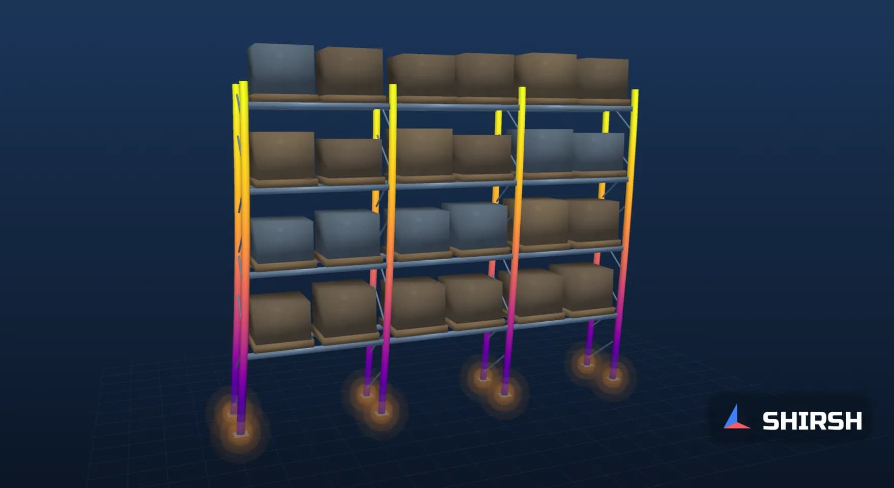
Rack Stability to IS 800: Base Fixity, Sway and the Upright Check
A pallet rack can pass every beam check and still be short on stability. We run a generic down-aisle frame with five base fixities under IS 800 notional loads: the beam moment stays at 4.05 kNm in every case while the frame buckling factor falls from 4.31 to 1.66 and second-order sway grows 3.67 times.
Read the full article below for the methodology, the data, and the engineering decisions behind it.
Ask a rack supplier how the design was checked and the answer usually starts with the beams: pallet weight, span, deflection limit, a beam table. Those numbers matter, and they are rarely where a selective pallet rack runs out of margin. In the down-aisle direction a rack is an unbraced frame. Its sway stiffness comes from the beam-to-upright connectors and from whatever rotational restraint the base plates and floor anchors give. Both are semi-rigid, both are uncertain, and most quick models replace them with rigid joints and fixed bases.
For this article we built a small down-aisle frame model and changed one thing at a time, the base fixity, to see what moves and what stays put. The rack is generic and the stiffness values are chosen for illustration, so the numbers belong to this model only. The pattern is the one we see when we review rack calculations.
1. What IS 800 asks for in a sway frame
IS 800:2007 handles frame imperfection with notional horizontal loads. Clause 4.3.6 sets them at 0.5 percent of the factored dead load plus vertical imposed load applied at each level, to account for practical imperfections, and clause 4.3.6.1 applies them in each orthogonal direction, one at a time, together with the factored gravity loads. They are not added to wind or seismic loads.
Clause 4.1.2 then separates non-sway frames, where relative lateral displacement of the member ends is effectively prevented, from sway frames, where it is not. A rack in the down-aisle direction, with no bracing behind it, falls in the second group. For such frames clause 4.4.2 allows a first-order elastic analysis with moment amplification, but where the amplification factor is greater than 1.4 it asks for a second-order elastic analysis to Annex B. Clause 7.2.2 points to Annex D for effective lengths when the analysis does not consider equilibrium in the deformed shape.
The code does not tell you what the connector or base stiffness is. That input comes from the rack system itself. The European rack standard EN 15512 takes both the beam-end connector and the floor connection stiffness from tests, which says something about how far a textbook "fixed" or "pinned" can be from the real joint. The cold-formed upright members are then checked to their own member rules; this article stays with the frame.
2. The worked example
The frame is one face of a three-bay rack: four uprights at 2,700 mm centres and four beam levels at 1,500 mm pitch, the top beam at 6,000 mm. Each bay level carries two 1,000 kg pallets, half of which goes to this face, and with a load factor of 1.5 that gives 14.7 kN per beam as a uniform load. The face carries 176.6 kN in total. The clause 4.3.6 notional load is 0.221 kN at each beam level.
The uprights have an area of 700 mm2 and an in-plane second moment of area of 1.0 x 10^6 mm4, the beams 500 mm2 and 1.6 x 10^6 mm4, and E is 200 GPa. Each beam-end connector is a rotational spring of 100 kNm/rad. The base of each upright is a rotational spring too, and that is the variable: fixed (case A), 200 kNm/rad (B), 50 kNm/rad (C), 20 kNm/rad (D) and pinned (E).

The down-aisle frame used in the worked example. Beam-end connectors and base springs are shown as circles. Red arrows are the IS 800 notional loads at each beam level.
We solved it with our own open-source plane frame model, beam-column elements with exact rotational springs at the connectors and bases: a linear buckling run under factored gravity for the elastic critical load factor, a first-order run under gravity plus notional loads, and a second-order run with the geometric stiffness updated until the axial forces settled. To check the model we built the same frame with rigid connectors in CalculiX, using quadratic beam elements with the same area and in-plane stiffness. With a fixed base CalculiX gave a critical load factor of 13.50 against 13.31 from our frame model, and with a pinned base 3.91 against 3.86. First-order top sway agreed within 1.9% in both. For case C, halving and doubling the number of elements did not change the critical load factor in the fourth significant figure.
3. Base fixity sets the frame's stability
Under factored gravity alone the fixed-base frame buckles at 4.31 times the load. A base spring of 200 kNm/rad brings that to 3.27, and the pinned base to 1.66. The bottom inner upright carries 58.9 kN in every case, so its elastic buckling load falls from 254.1 kN to 98.1 kN, and the effective length that goes with it rises from 1.86 to 2.99 times the 1.5 m storey height.

Left: elastic critical load factor of the frame under factored gravity for the five base conditions. The dashed line is where the familiar sway amplifier 1/(1 - 1/λcr) reaches 1.4. Right: effective length of the bottom inner upright from the buckling run, as a multiple of storey height.
The sway amplifier 1/(1 - 1/λcr) passes 1.4 when λcr drops below 3.5. Only the fixed base stays above that line. IS 800 works out its amplification factors member by member, through clause 9.3.2.2, so this frame-level estimate is a guide rather than the code figure. Still, if sway is amplified this much, a first-order analysis with amplified moments is outside the range where clause 4.4.2 lets the designer stop.
Case | Base, kNm/rad | λcr | 1/(1 - 1/λcr) | Top sway, first-order, mm | Top sway, second-order, mm | Second / first | Upright effective length / storey |
|---|---|---|---|---|---|---|---|
A | fixed | 4.31 | 1.30 | 6.23 | 8.07 | 1.29 | 1.86 |
B | 200 | 3.27 | 1.44 | 8.12 | 11.51 | 1.42 | 2.13 |
C | 50 | 2.30 | 1.77 | 10.26 | 17.38 | 1.69 | 2.54 |
D | 20 | 1.95 | 2.06 | 11.45 | 22.19 | 1.94 | 2.76 |
E | pinned | 1.66 | 2.51 | 12.73 | 29.61 | 2.33 | 2.99 |
Two things in the table are worth a second look. The amplifier formula tracks the computed second-order growth closely while λcr is high (1.30 against 1.29 for case A) and drifts away as it falls (2.51 against 2.33 for case E). It is an estimate of the frame response, so once λcr is low the second-order run is the number to trust. And the second-order sway at the top of the pinned-base frame is 3.67 times that of the fixed-base one, from the same loads.
4. What the beams see: almost nothing changes
The largest beam moment in the frame is 4.05 kNm in all five cases. It sits at midspan, it is set by the span, the load and the connector stiffness, and the base condition does not reach it. A simply supported beam would see 4.97 kNm; the semi-rigid connectors take the difference.

Three results as ratios to the fixed-base case. The beam moment does not move; the upright buckling load and the second-order sway move a great deal.
This is the reason a rack that "passes the beam check" can still be short on stability. The beam check is a local member check on a well-defined span. The upright check depends on an effective length that comes out of the frame, and the frame depends on two stiffnesses that a simple model usually assumes. In this example the upright's elastic buckling load falls by almost half between a fixed base and a 50 kNm/rad base, while the beam does not notice.
5. The trap: rigid joints and fixed bases
The CalculiX check in section 2 used rigid connectors on purpose, because that is what a quick frame model often does. With rigid connectors and a fixed base this frame has λcr of 13.31. With 100 kNm/rad connectors and the same fixed base it has 4.31. The same structure, modelled with two convenient assumptions, looks about three times more stable than it is.
A λcr of 13.31 would also put the frame comfortably above the 10 that EN 1993-1-1 clause 5.2.1(3) uses to allow first-order elastic analysis. A designer could then skip the second-order run altogether, on the strength of joints that the rack does not have.

Left and centre: first buckling modes of the frame with a fixed base and a pinned base, shape scaled for clarity. Right: top-level sway under factored gravity plus the IS 800 notional loads, first-order and second-order, for the five base conditions.
The base moment tells the other half of the story. In the fixed-base frame the second-order moment at the base reaches 0.58 kNm, and the base plate and floor anchors have to carry it. At 50 kNm/rad the largest base moment is 0.24 kNm and at 20 kNm/rad it is 0.14 kNm: a softer base takes less moment and the frame sways more instead. A model with a fixed base and a base plate detail that cannot carry 0.58 kNm is internally inconsistent, and that inconsistency rarely shows up in a beam table.
6. Where the peaks sit
We checked where the largest upright moment falls before quoting it. For cases A to D it is at the top of the right-hand end upright, at 6,000 mm, where the top beam's connector hogging moment enters the upright: 0.96 kNm for the fixed base, rising only to 1.00 kNm for 20 kNm/rad. With a pinned base it moves to the first beam level of the same upright, at 1,500 mm, and reaches 1.17 kNm, because the base can no longer take any of the sway moment. The largest connector moment rises from 1.12 kNm (case A) to 1.53 kNm (case E), so a softer base also asks more of the connectors.
The notional loads in this example are small, 0.5 percent of the vertical load, and so the second-order moments grow modestly in absolute terms. The frame property that changes most is its stiffness, and with it the upright's effective length and capacity. In a real rack, out-of-plumb erection and connector looseness add to the initial sway, and racking standards that ask for those to be included will push these moments up further. IS 800 Table 33 allows a column inclination of 0.002 times the storey height between floors in multi-storey steelwork, which gives a sense of how small the tolerated tilt is compared with what a loose connector can produce.
7. What to ask for in a rack stability check
The connector and base rotational stiffness values used, with their source: a test report, the supplier's data, or a stated assumption with a sensitivity run.
The elastic critical load factor of the down-aisle frame under factored gravity, and the decision it drives under IS 800 clause 4.4.2.
Notional loads to clause 4.3.6 applied with the factored gravity loads, or an equivalent initial sway, stated clearly.
Upright effective lengths that come from the frame (a buckling run or Annex D with realistic restraint), not a default factor.
Base moments and connector moments from the same analysis, checked against the base plate, anchors and connector capacity.
A cross-check of the model against an independent run or a simple hand case, as we did with CalculiX here.
If a calculation shows only beam utilisation and a deflection check, the stability question has not been answered.
Where Shirsh fits
At Shirsh Technosolutions we check pallet racking, shelving and mezzanine structures for stability, with second-order frame models in ANSYS Mechanical or open-source codes, and we test the effect of connector and base stiffness rather than assume it. If you have a rack design to verify or a rack that has been loaded beyond its original plan, please get in touch.
References
IS 800:2007, General Construction in Steel, Code of Practice (Third Revision): clause 4.1.2 (sway and non-sway frames), 4.3.6 and 4.3.6.1 (notional horizontal loads), 4.4.2 (first-order analysis with amplification, second-order analysis to Annex B when the amplification factor exceeds 1.4), 7.2.2 and Annex D (effective length), Table 33 (erection tolerances).
EN 1993-1-1, Eurocode 3: Design of steel structures, General rules and rules for buildings, clause 5.2.1(3) (first-order analysis permitted for elastic analysis when αcr is at least 10).
EN 15512, Steel static storage systems, Adjustable pallet racking systems, Principles for structural design (connector and floor connection stiffness from tests).
Worked example computed for this article on 20 November 2026: in-house open-source plane beam-column model with rotational springs, checked against CalculiX B32R beams for rigid connectors. Generic three-bay, four-level rack; not any project.
Click to view full size
Related case studies

Want to Apply This to Your Product?
Our engineers can help you implement these techniques on your specific components and assemblies.
Get insights like this in your inbox
Engineering deep-dives, simulation tips, and industry analysis. No spam, unsubscribe any time.