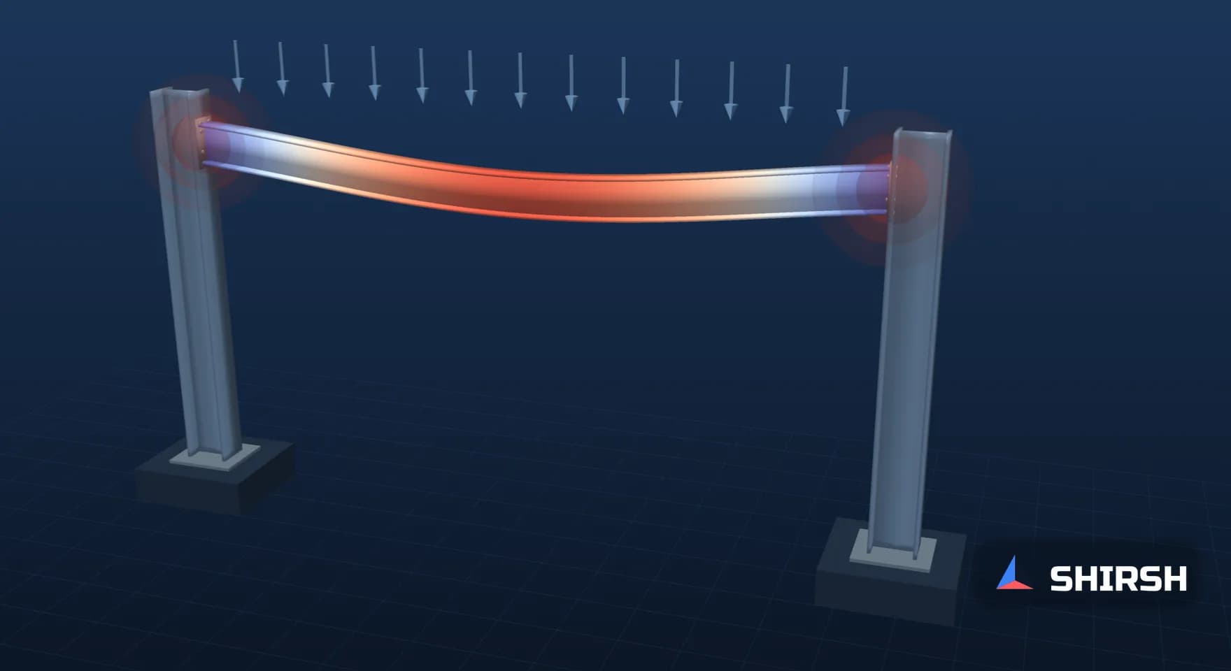
Fixed Supports in FEA: The Assumption That Quietly Moves the Answer
A fixed support is often the one input in an FEA model that nobody measured. EN 1993-1-8 calls a joint rigid at a stiffness of 8 and pinned at 0.5, and on a simple beam that range moves the midspan moment by 1.4 times and puts 20% of the fixed-end moment into a "pinned" connection. I set out what I ask to see about supports in a report.
Read the full article below for the methodology, the data, and the engineering decisions behind it.
Almost every structural FEA model I open has a fixed support somewhere in it. It goes on in a few seconds, the solver is happy, and nobody comes back to it. Yet of all the inputs in the model, it is often the only one that nobody measured or calculated.
A fixed support says the face it is applied to cannot move or rotate at all, whatever load arrives. No base plate or bolted end plate behaves like that. Most of the time the difference is small enough to ignore. Sometimes it decides where the moment goes, and then the support is the most important assumption in the report.
1. The steel code already admits that "rigid" is a range
EN 1993-1-8, the Eurocode part for steel joints, is honest about this. Clause 5.2.2.5 classifies a beam-to-column joint by its initial rotational stiffness, written relative to the beam as S·L/(E·I). A joint is rigid if that ratio is at least 8 in a frame where the bracing cuts horizontal displacement by at least 80%, or at least 25 in other frames, provided the beam to column stiffness ratio is at least 0.1 in every storey. It is nominally pinned if the ratio is 0.5 or less. Everything in between is semi-rigid.
So the code accepts a joint with a finite stiffness of 8 as "rigid", and one with a stiffness of 0.5 as "pinned". I wanted to see what those two words mean for the numbers in a report, so I worked out the simplest case I could: a beam of span L under a uniform load w, with an equal rotational spring at each end. The closed-form result was checked against a 40-element beam model and the two agreed to within rounding.
End stiffness S·L/(E·I) | End moment, % of fully fixed (wL²/12) | Midspan moment, % of simply supported (wL²/8) | Midspan deflection, % of simply supported |
|---|---|---|---|
0, true pin | 0 | 100 | 100 |
0.5, limit for "nominally pinned" | 20.0 | 86.7 | 84.0 |
2, semi-rigid | 50.0 | 66.7 | 60.0 |
8, limit for "rigid", braced frame | 80.0 | 46.7 | 36.0 |
25, limit for "rigid", other frames | 92.6 | 38.3 | 25.9 |
Infinite, a fixed support in FEA | 100 | 33.3 | 20.0 |

Uniformly loaded beam with equal rotational springs at both ends, closed form checked against a beam element model, computed for this article. The shaded bands are the EN 1993-1-8 clause 5.2.2.5 zones for a beam-to-column joint.
Two rows matter most to me. At the braced-frame limit for a rigid joint, the end moment is 80% of the fixed value, while the midspan moment is 1.4 times and the deflection 1.8 times what the fixed model reports. A designer who sized the beam for midspan from a fixed-support model is on the wrong side of that. At the other end, a joint the code lets you call pinned still draws 20% of the fixed-end moment. The beam is fine with that. The connection, designed for shear alone, may not be.
2. Why the error is quiet
The trouble with a fixed support is that its mistakes rarely show up as anything strange on the screen. The contour plot looks clean and the reactions balance the load. Deflections are smaller than expected, which reads as good news. A stiffer support raises the natural frequencies too, so a modal check can pass on stiffness that the real base does not have.
And the peak stress tends to sit right at the edge of the fixed face, where the support itself creates it. We wrote about that in an earlier Insight on stress singularities, so I won't repeat it here. The point for this note is that the place the model says is most stressed is often the place where the model is least like the structure.
Column bases deserve their own mention. EN 1993-1-8 gives them separate limits in clause 5.2.2.5(2), and in practice their stiffness depends on the plate and anchors as much as on the concrete beneath. A fixed support at the bottom of a column or a skid leg makes a claim about all of that, usually without anyone having looked.
3. What I ask for in a report
A sentence on every support saying what it represents and why it was chosen. "Fixed at base plate" is a description of the button that was pressed. "Base modelled as fixed because the column base was designed as rigid to EN 1993-1-8, with stiffness from the component method of section 6.3" is an engineering assumption I can review.
Where the stiffness is uncertain, two runs instead of one. Pinned and fixed, or a spring at the low and high end of a credible range. If the decision, a member size or a pass on a frequency check, is the same at both ends, the support question is closed and the report can say so in a line. If it isn't, the connection needs to be modelled properly, with its plates and bolts in ANSYS Mechanical or in Code_Aster, or given a calculated stiffness.
The reaction moments, tabulated, at every support that was fixed. These are the loads the connection has to carry. If the connection drawing shows a simple shear tab, those moments either go somewhere the model did not show or the model was wrong.
Where the solver offers it, the support type that matches the hardware. ANSYS Mechanical has frictionless, compression-only and remote displacement supports, and bolted contact for the joint itself. A base plate that can lift at one edge is closer to compression-only contact than to a fixed face, and the answer can change accordingly.
4. A support is a load path decision
I think of a boundary condition as the point where the model hands its loads to the rest of the world. Choosing fixed means choosing that the moment goes into the support. Choosing pinned means it stays in the span. Both are fine engineering choices when they are made on purpose and written down. What I push back on is the fixed support that was never a choice at all, because it was the default.
The table above is a deliberately simple case, a single beam with equal ends. Real frames redistribute moment between members, and plated structures and brackets are less tidy still. The direction of the error does carry over, though. Stiffer supports than the real ones pull moment towards the connections and away from the span, and make deflections and frequencies look better than they will be on site.
Where Shirsh fits
At Shirsh Technosolutions we build structural FEA models in ANSYS Mechanical and in open-source codes such as Code_Aster and CalculiX, with supports and connections modelled to suit the decision being made, and we review models and reports prepared by others. If a result in one of your reports depends on how something is held, please get in touch and we can look at it together.
References: EN 1993-1-8:2005, Eurocode 3, Design of steel structures, Part 1-8: Design of joints (clause 5.2.2.5, classification by stiffness: rigid where Sj,ini ≥ kbEIb/Lb with kb = 8 for frames whose bracing reduces horizontal displacement by at least 80% and 25 for other frames provided Kb/Kc ≥ 0.1; nominally pinned where Sj,ini ≤ 0.5EIb/Lb; column bases in 5.2.2.5(2); initial stiffness by the component method in section 6.3). Worked check computed for this article on 18 November 2026: uniformly loaded beam with equal rotational end springs, closed-form slope compatibility, end moment = (wL²/12)·α/(α + 2) with α = S·L/(E·I), confirmed with a 40-element Euler-Bernoulli beam model. Generic geometry; not any project.
Click to view full size
Related case studies
Want to Apply This to Your Product?
Our engineers can help you implement these techniques on your specific components and assemblies.
Get insights like this in your inbox
Engineering deep-dives, simulation tips, and industry analysis. No spam, unsubscribe any time.