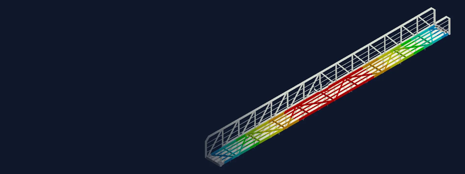
Aluminium Marina Gangway FEA to Eurocode 9: Strength Check and Hinge Redesign
FEA of an aluminium marina gangway on floating pontoons to Eurocode 9: buckling, strength and deflection checks, and a hinge zone fix verified in ANSYS.
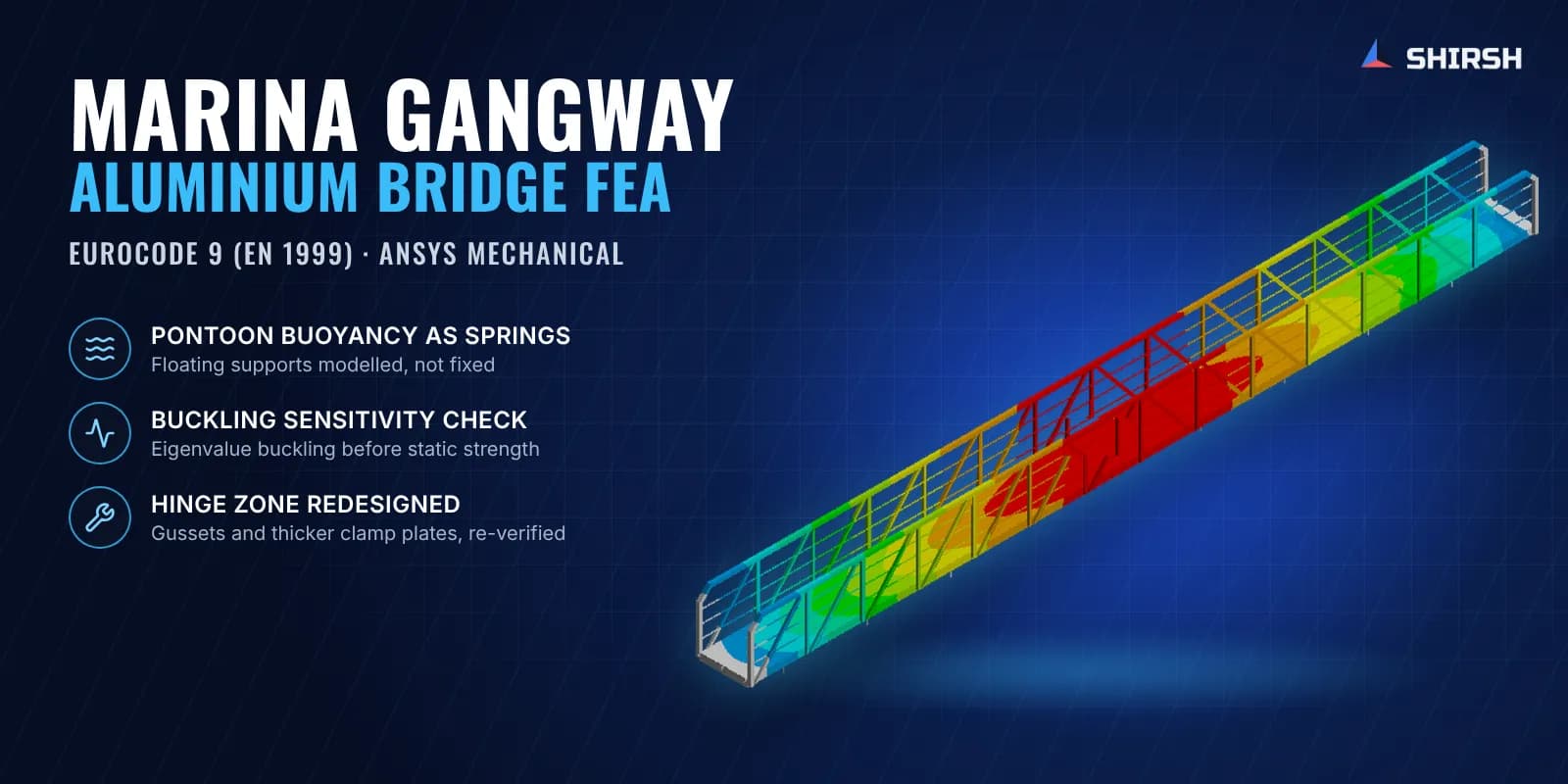
Project brief
A pontoon and marina equipment maker in Europe needed proof that a long aluminium gangway, the walkway that links a floating pontoon line to the shore, would carry its design pedestrian load safely. The bridge is a welded truss in 6005A aluminium with a GRP grating deck, hinged at one end and sitting on pontoons along its length.
Shirsh Technosolutions carried out an aluminium gangway FEA in ANSYS Mechanical, checked strength and deflection against Eurocode 9 (EN 1999), found that the hinge zone of the first design did not meet the ultimate limit state, and then verified a simple fix on the full model.
What was at risk
Marina gangways look simple, but they are slender aluminium trusses carrying crowds over water, and the loads end up in a few small details. Hinge plates and clamps at the shore end, where the whole span is held, are the usual weak point.
Aluminium also behaves differently from steel. Its stiffness is about a third of steel's, so deflection and stability can govern before stress does, and welded 6xxx alloys lose strength near the welds. A hand calculation on the main truss will not show what happens inside a hinge plate.
The supports add their own question. The bridge does not sit on rigid bearings. Part of it rests on floating pontoons that sink a little under load, and that changes how the load shares between the hinge and the deck frame.
The client needed:
a clear answer on strength and deflection under dead load and the full pedestrian live load
the location of any overstressed detail, with a practical change if the design fell short
a model they could trust, with buoyant supports represented properly
Solution offered
Building the model. The 3D model was built from the client's 2D drawings, including the side trusses, handrails, deck profiles, cross members, clamps and hinge plates. We meshed it with second-order solid elements and treated the joints as bonded or frictional contacts, depending on how each part is actually connected. Mesh quality was checked for aspect ratio, Jacobian ratio and warping, and the reported error stayed within the usual FEA guidance in the general regions.
Loads and supports. Self weight came directly from the 6005A aluminium density, the GRP grating was added as a distributed mass, and the pedestrian live load was applied as a uniform pressure over the walkway area. The hinge and roller ends were modelled with remote displacement supports at the real hinge plates. Under the deck, the pontoons were replaced by springs, with a stiffness worked out from the total load and the expected pontoon sinkage, so the frame could settle on its floating supports as it would on the water.
Stability first. Before the strength run we did an eigenvalue buckling analysis of the whole bridge. In Eurocode 9 terms, the critical load factor tells you how sensitive a frame is to instability and whether second-order effects need attention. It also shows the first buckling shapes, so we could see which members to watch.
Strength and deflection. A static structural run under dead plus live load gave total deformation and equivalent stress for the full bridge and for each deck profile. Mid-span deflection was compared with a span/500 serviceability limit. Peak stress was compared with the aluminium strength using the EN 1999 partial factor.
Finding and fixing the weak spot. On the first design, deflection was within the limit, but the hinge plate area at the shore end did not meet the ultimate limit state. The stress plots showed a sharp concentration where the plate meets the frame. We reported this to the client and proposed two changes at that zone: gussets added near the hinge plates, and a thicker clamp plate. The revised geometry was re-run straight away. Peak stress at the hinge came down sharply, the partial factor check passed with margin, and deflection stayed within the limit. The final report and the updated 3D geometry were issued to the client.
Common questions
How do you check an aluminium gangway or footbridge to Eurocode 9? Build a detailed FE model of the truss, deck and connections, apply self weight and the pedestrian live load, and check stress against the aluminium strength with the EN 1999 partial factor and deflection against a span-based limit. Run an eigenvalue buckling check too, because aluminium frames are slender and stability can govern.
How are floating pontoon supports modelled in a gangway FEA? Replace each pontoon with a vertical spring. The stiffness comes from the load the pontoons carry and how far they are allowed to sink, so the bridge settles on its supports realistically instead of sitting on rigid bearings.
Challenges we overcame
Slender aluminium truss where stability and deflection can govern before stress
Floating pontoon supports that settle under load, modelled as springs instead of rigid bearings
Load concentrated into small hinge plates and clamps at the shore end
First design failing the ultimate limit state at the hinge while passing on deflection
A design fix that had to be re-checked on the full bridge as well as at the plate
How we executed
- 1
Built the 3D model of the gangway from the client's 2D drawings, including hinge plates and clamps
- 2
Meshed with second-order solid elements and checked mesh quality
- 3
Applied self weight, GRP grating weight and the pedestrian live load as a pressure on the walkway
- 4
Modelled hinge and roller ends with remote supports and pontoons as buoyancy springs
- 5
Ran eigenvalue buckling to assess the frame's sensitivity to instability
- 6
Ran static strength and deflection checks against Eurocode 9 and a span/500 limit
- 7
Located the overstressed hinge plate zone and proposed gussets with a thicker clamp plate
- 8
Re-ran the revised geometry, confirmed the checks, and issued the final report and updated 3D geometry
Project outcome
The redesigned gangway met the Eurocode 9 strength check at the hinge zone with margin, and deflection stayed within the span/500 limit.
The weak detail was found in the model, not on the water, and fixed with two small changes: gussets and a thicker clamp plate.
Peak stress at the hinge zone came down sharply compared with the original design.
The client received the final report and the revised 3D geometry of the bridge.
Project gallery
Where this lives
Software used
Related solutions
Industries
At a glance
We apply the same rigour to every engagement
Let us show you what's possible for your product.