An Eigenvalue Is Not a Capacity: Reading FEA Buckling Results
An eigenvalue load factor of 3 can look like a safe margin, yet on a thin cylinder it may sit close to the real lower bound. I set out what a linear buckling analysis can claim, how EN 1993-1-6 builds imperfections back in, and what I ask to see in a buckling report.
When a buckling result lands on my desk, the first number I look for is the load factor from the eigenvalue run. A value of 3 or 5 against the design load reads like a comfortable margin, and I can see why a report would stop there. I usually can't. An eigenvalue is a property of a perfect structure, and the structures we build are never perfect.
This is not an argument against eigenvalue analysis. I use it on almost every job where compression matters. My point is narrower: the number it gives is a reference, and a report has to say how that reference was turned into a resistance.
1. What the eigenvalue actually is
EN 1993-1-6, the Eurocode part for steel shells, gives the plainest definitions I know. A linear elastic bifurcation analysis, LBA in its terms, finds the lowest eigenvalue at which the structure may buckle, on the perfect geometry, with small-deflection theory and linear elastic material (clause 2.2.5). Nothing in that definition mentions imperfections, residual stress or yielding, because none of them are in the calculation.
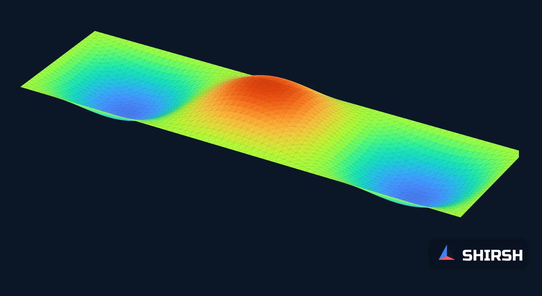
Within its own assumptions, LBA is very good. For this note I ran a small check in scikit-fem: a simply supported rectangular plate under uniform compression along its length, solved with plate bending elements. The textbook buckling coefficient for this plate is 4.0 when the length is a whole multiple of the width. On the square plate the model gave 3.8375 on an 8 by 8 mesh, 3.9581 on 16 by 16 and 3.9894 on 32 by 32, within 0.27% of the classical value. The plate three times as long as it is wide gave the same coefficients and buckled in three half-waves, the shape on the cover of this article.

First buckling modes from the scikit-fem eigenvalue run: Morley plate elements, simply supported edges, uniform compression along x, 32 elements per unit width. Contours show the normalised out-of-plane deflection. Each plate buckles in one half-wave per square, and all three give k = 3.9894.
So the eigenvalue solver is not the weak point. The question is what the perfect plate, or the perfect shell, has to do with the one fabricated in a workshop.
2. Where the perfect answer is a long way off
For a flat plate the gap between the perfect and the real answer is usually modest. For a thin cylinder in axial compression it is large, and it has been known to be large for decades. The classical formula for the perfect cylinder gives a buckling stress of about 0.605 Et/R for a Poisson's ratio of 0.3. Tests on real cylinders fall well below it, and the scatter widens as the shell gets thinner.
NASA SP-8007, the design monograph on buckling of thin-walled circular cylinders, handled this with an empirical lower-bound knockdown factor that falls as the radius to thickness ratio rises. I worked it out for four ratios.
R/t | NASA SP-8007 knockdown factor | Perfect-shell eigenvalue overstates the lower bound by |
|---|---|---|
100 | 0.581 | 1.72 times |
250 | 0.434 | 2.30 times |
500 | 0.322 | 3.11 times |
1000 | 0.224 | 4.46 times |

The NASA SP-8007 lower-bound knockdown for axially compressed cylinders, computed for this note. The dashed line is what a perfect-shell eigenvalue analysis would report. These are elastic fractions; on thicker shells, yielding starts to govern as well.
On a silo or tank wall at R/t of 500, an eigenvalue factor of 3 on the design load is roughly what this lower bound would leave at 1. That is the reason I don't accept "LBA factor greater than 1" as a buckling check on a shell.
3. How the code builds the imperfection back in
EN 1993-1-6 doesn't ask designers to guess. It ties the reduction to the fabrication tolerance quality class the designer assumes: Class A excellent, Class B high, Class C normal. In Annex D the meridional fabrication quality parameter Q is 40, 25 and 16 for the three classes (Table D.2), and the elastic imperfection reduction factor for circumferential compression and for shear is 0.75, 0.65 and 0.50 (Tables D.5 and D.6). A design checked as Class A is only valid if the shell is built and inspected to Class A tolerances. I want that class written on the drawings as well as in the calculation.
The code also lays out a ladder of analyses, each with a defined scope (clauses 2.2.4 to 2.2.10).
Analysis (EN 1993-1-6) | Geometry and material | What I would let it claim |
|---|---|---|
LA, linear elastic | Perfect, small deflection, elastic | Stresses for the plastic and fatigue checks; no buckling claim |
LBA, bifurcation | Perfect, elastic, eigenvalue | The elastic critical reference and the mode shape |
MNA, materially nonlinear | Perfect, small deflection, elasto-plastic | The plastic reference resistance |
GNA and GMNA | Perfect, large deflection, elastic or elasto-plastic | How the perfect shell behaves; the baseline for imperfection sensitivity |
GNIA and GMNIA | Imperfect, large deflection, elastic or elasto-plastic | A buckling resistance, once the imperfection shape and amplitude are justified and the method is checked against known cases |
Clause 2.2.10 points to a step I find many reports skip. When a GMNIA is run, the eigenvalues are to be checked and a GMNA of the perfect shell run alongside, so that the effect of the imperfection is visible instead of buried. A GMNIA with one arbitrary imperfection amplitude and no perfect-shell comparison tells me very little about how close to the edge the structure sits.
4. What I ask to see in a buckling report
On plated steelwork, racks, frames and shells alike, my requests are much the same.
The first few mode shapes, plotted, with the load factor for each and the load case it belongs to. A first mode that sits in a local detail nobody intended to check is information, and so is a cluster of modes with nearly equal factors, which usually means the structure is sensitive to imperfections.
A plain statement of what the eigenvalue was used for. If it fed a code formula as the elastic critical value, the report should name the formula. If it was used directly as a margin, I will ask why.
For any nonlinear run, the imperfection shape, its amplitude and where the amplitude came from, the fabrication class assumed, and the load-displacement curve up to and past the peak. A resistance quoted from a solver that simply stopped converging is not a peak.
A mesh check on the buckling load itself. The plate above moved by about 4% between the coarsest and the finest mesh, and shells with short wavelength modes can need much finer meshes than the stress check did.
Where Shirsh fits
At Shirsh Technosolutions we run eigenvalue and full nonlinear buckling analyses in ANSYS Mechanical and in open-source codes such as Code_Aster and CalculiX, for plated structures, shells, racks and frames, and we review buckling reports prepared by others. If you have a load factor in a report and are not sure what it is allowed to mean, please get in touch.
References: EN 1993-1-6:2007, Eurocode 3, Design of steel structures, Part 1-6: Strength and stability of shell structures (clauses 2.2.4 to 2.2.10, types of analysis; Annex D, Tables D.2, D.5 and D.6). NASA SP-8007, Buckling of Thin-Walled Circular Cylinders, NASA Space Vehicle Design Criteria (empirical knockdown factor for axial compression, 1 - 0.901(1 - e^-φ) with φ = (R/t)^0.5 / 16). S. P. Timoshenko and J. M. Gere, Theory of Elastic Stability (classical buckling of simply supported plates, k = 4.0; classical axial buckling of cylinders). Worked check computed for this article on 14 November 2026: scikit-fem, Morley plate elements, simply supported plates of aspect ratio 1, 2 and 3 on three meshes, and the NASA SP-8007 factor at four R/t values. Generic geometry; not any project.
Related case studies


Want to Apply This to Your Product?
Our engineers can help you implement these techniques on your specific components and assemblies.
Get insights like this in your inbox
Engineering deep-dives, simulation tips, and industry analysis. No spam, unsubscribe any time.