
Parametric CAD & 3D Modeling
Parametric CAD from concept models and legacy drawings, with geometry made ready for simulation.
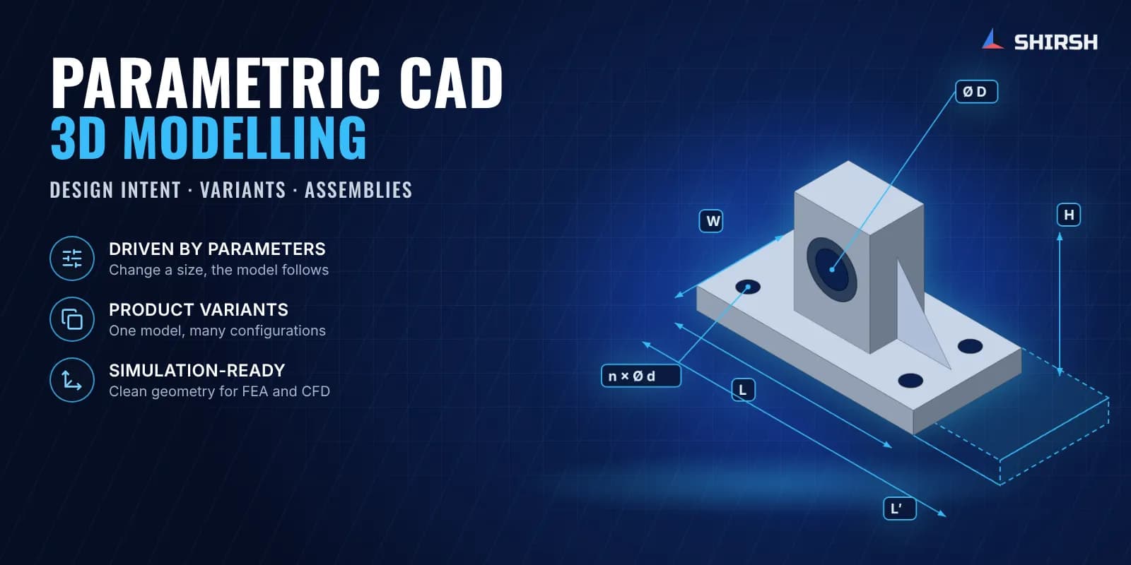
What this solution covers
CAD is the starting point of every simulation we run. We build parametric 3D models with clear design intent, and we prepare the geometry so it goes into FEA and CFD meshing without a cleanup round.
Pain points we address
Legacy products exist only as 2D drawings or physical samples with no digital CAD model
CAD models from design teams contain features that cause meshing failures in FEA/CFD
No parametric design intent, so a geometry change means a manual rebuild instead of a parameter update
Multi-CAD environments create translation errors when importing STEP/IGES files
What we solve
Full parametric 3D modeling from 2D drawings, sketches, or reverse-engineered scan data
Geometry cleanup and defeaturing for simulation-ready mesh generation
Mid-surface extraction from solid bodies for shell-element FEA modeling
Design table-driven configurations for parametric variant generation
How we approach it
- 1
Requirements review: confirm what the model is for, whether manufacturing drawings, FEA, CFD or visuals
- 2
Modelling strategy: plan the feature tree, datums and design intent so the model flexes as expected
- 3
Modelling: fully constrained parts and assemblies built in a clean feature order
- 4
Simulation preparation: defeature, extract mid-surfaces, create named selections and export in the target format (Parasolid, STEP or native)
- 5
Quality check: geometry checks and a test mesh in the target solver before delivery
Deliverables
Native parametric part and assembly files with full feature history
GD&T-compliant 2D manufacturing drawings where required
Defeatured and mid-surfaced geometry ready for FEA
Fluid volumes extracted for CFD
Parameter table for configuration control
Expected outcomes
Geometry that goes straight into meshing, without days of cleanup
Parametric models that let you try design variants without a rebuild
Legacy products archived as associative 3D models with manufacturing drawings
One CAD standard across a multi-engineer project
Why Shirsh
Simulation can only be as good as the geometry behind it. Our modellers know what FEA meshing and CFD domain extraction need downstream. Every model is built with that in mind: clean topology, named selections and the right level of defeaturing.
Where this lives
Want to learn this?
We also offer ANSYS & SolidWorks training courses.
At a glance
Discuss your project with our engineers
Tell us about your simulation, validation or design challenge.