Nozzle Loads on Vessels: Where the Hand Method Stops and FEA Starts
Hand checks for nozzle loads hold well on the nozzle neck, within 2.0% of our finite element model. At the junction they can miss where the stress governs: on a generic shell the nozzle wall carried up to 1.98 times the shell value, and a 114 mm nozzle reached 418.55 MPa where the shell side showed 322.17 MPa.
Read the full article below for the methodology, the data, and the engineering decisions behind it.
Most nozzle load checks on pressure vessels start with a piping engineer's load table and end with a WRC calculation. Six numbers go in, a radial force, two shears, two bending moments and a torsion, and stresses come out at a handful of points around the nozzle. For a small nozzle on a thick shell that is usually all the job needs. The trouble starts when the same routine is used on a geometry the method was never built for, or when the report only shows the stresses the method happens to calculate.
We built a small finite element study for this article to see where that line falls. It is a generic radial nozzle on a cylindrical shell, solved for four nozzle sizes under the same loads. The numbers belong to this model only. The pattern they show is one we meet in real nozzle load reviews.
1. What the hand methods do, and what they leave out
The usual hand routes are the Welding Research Council bulletins. WRC 107, and WRC 537 which re-expresses its curves as equations, comes from Bijlaard's shell solutions. It gives membrane and bending stresses in the shell at the edge of the attachment, at points on the longitudinal and transverse planes through the nozzle, on the outside and inside surfaces. WRC 297 covers cylinder-to-cylinder junctions and also gives stresses in the nozzle wall. Neither bulletin includes the stress from internal pressure, which has to be found and combined separately.
Both methods are curve fits over a range of geometry. Published summaries of the bulletins do not agree on the exact limits; for WRC 107 we have seen a nozzle-to-shell diameter ratio of 0.33 quoted in one place and 0.5 in another, so the limit should be read from the bulletin itself. Common design software stops when a case falls outside the curves rather than extrapolating. What the summaries do agree on is what the methods cannot see: a nozzle close to another nozzle, a head or a support, a reinforcing pad, a non-circular attachment, and anything between the four planes where the stresses are reported.
The other hand check is plain beam theory on the nozzle neck: axial force over area, and moment times radius over the second moment of area. It is quick and correct away from the shell. Our question was how far it can be trusted near the junction.
2. The worked example
The shell has an inside radius of 500 mm and a 12 mm wall, so its mean diameter is 1,012 mm. We modelled 1,600 mm of it with both ends fixed. A radial nozzle with an 8 mm wall stands 400 mm above the top of the shell, with a 6 mm outside weld fillet at the junction. Four nozzle sizes were run: 114, 219, 406 and 610 mm outside diameter, which gives nozzle-to-shell diameter ratios of 0.113, 0.216, 0.401 and 0.603.
Three loads were applied separately at the nozzle end: a radial pull P of 10 kN, a longitudinal moment ML of 5 kN·m that bends the nozzle along the shell axis, and a circumferential moment MC of 5 kN·m that bends it across the shell. The material is linear elastic with E = 200 GPa and Poisson's ratio 0.3. Each case was solved as a quarter model, with symmetry or antisymmetry conditions on the two planes as the load requires, using quadratic tetrahedra in CalculiX. The elements in the weld fillet are 1.6 mm, so the 8 mm nozzle wall and 12 mm shell wall have several elements through the thickness at the junction.

The model in section through the transverse plane, with the three loads and the two stress classification lines (SCLs) used at each position around the nozzle: one through the nozzle wall just above the fillet toe and one through the shell just beyond it.
Stresses were linearised on the two SCLs by the stress integration method of ASME Section VIII Division 2, Annex 5-A. We use 0° for the longitudinal plane (along the shell axis) and 90° for the transverse plane (across it).
3. Where the hand check holds: the nozzle neck
Halfway up the nozzle, 300 mm above the top of the shell, the finite element membrane stress in the nozzle wall agrees with beam theory for every case. For the radial load we averaged around the nozzle, because the stress there still varies a little from 0° to 90°; for the moments we read it on the plane of bending.
Nozzle OD, mm | P: hand P/A, MPa | P: FE, MPa | ML: hand M·r/I, MPa | ML: FE, MPa | MC: FE, MPa |
|---|---|---|---|---|---|
114 | 3.75 | 3.76 | 70.42 | 69.58 | 70.15 |
219 | 1.89 | 1.90 | 17.85 | 17.96 | 17.77 |
406 | 1.00 | 1.00 | 5.02 | 4.92 | 5.09 |
610 | 0.66 | 0.66 | 2.20 | 2.16 | 2.23 |
The largest difference is 2.0%. This is a useful check on any nozzle model before its junction results are read, since it confirms the loads went in at the right size and the right sign. It says nothing yet about the junction.
4. At the junction, the nozzle wall governs
The table below gives the highest linearised membrane plus bending stress on each side of the fillet toe, taking the larger of the 0° and 90° positions.
Nozzle OD, mm | P: shell / nozzle, MPa | ML: shell / nozzle, MPa | MC: shell / nozzle, MPa |
|---|---|---|---|
114 | 36.22 / 43.81 | 237.01 / 292.09 | 322.17 / 418.55 |
219 | 20.24 / 31.86 | 78.70 / 119.19 | 146.17 / 229.90 |
406 | 9.06 / 16.97 | 21.52 / 36.81 | 53.34 / 99.62 |
610 | 5.77 / 11.62 | 8.97 / 16.71 | 21.86 / 43.36 |
In all twelve cases the nozzle side is higher. Under MC the nozzle wall carries 1.30 times the shell value on the smallest nozzle and 1.98 times on the largest. That follows from the geometry here, an 8 mm nozzle on a 12 mm shell, and it is common in practice because nozzle necks are often thinner than the shell they sit in. A method that reports shell stresses only would miss the governing location in every one of these cases.

Governing linearised membrane plus bending on the shell side and the nozzle side of the fillet toe, for the two moments, with the nominal neck bending stress from beam theory marked for comparison.
To see what that means for an assessment, take an example allowable S of 138 MPa, so 1.5S is 207 MPa and 3S is 414 MPa. In Part 5, 1.5S is the limit for local primary membrane plus bending, and 3S is the usual value of SPS for the range of primary plus secondary stress. On the 114 mm nozzle under MC, the shell side reaches 322.17 MPa, which is inside 3S. The nozzle side reaches 418.55 MPa, which is not. The local membrane on that nozzle-side line is 153.76 MPa, inside 1.5S. Whether the bending is then held to 1.5S or to 3S depends on how the load and the stress are classified under Table 5.6, and that decision has to be written into the report. A check that never looks at the nozzle wall does not reach that question at all.
5. The highest stress is not always on 0° or 90°
Under MC and P the peak von Mises stress sits in the weld fillet at or close to 90° for every nozzle size, which is where a four-point method looks. Under ML it moves. The peak was at 2.3° on the 114 mm nozzle, 21.2° on the 219 mm nozzle, 27.5° on the 406 mm nozzle and 6.2° on the 610 mm nozzle.

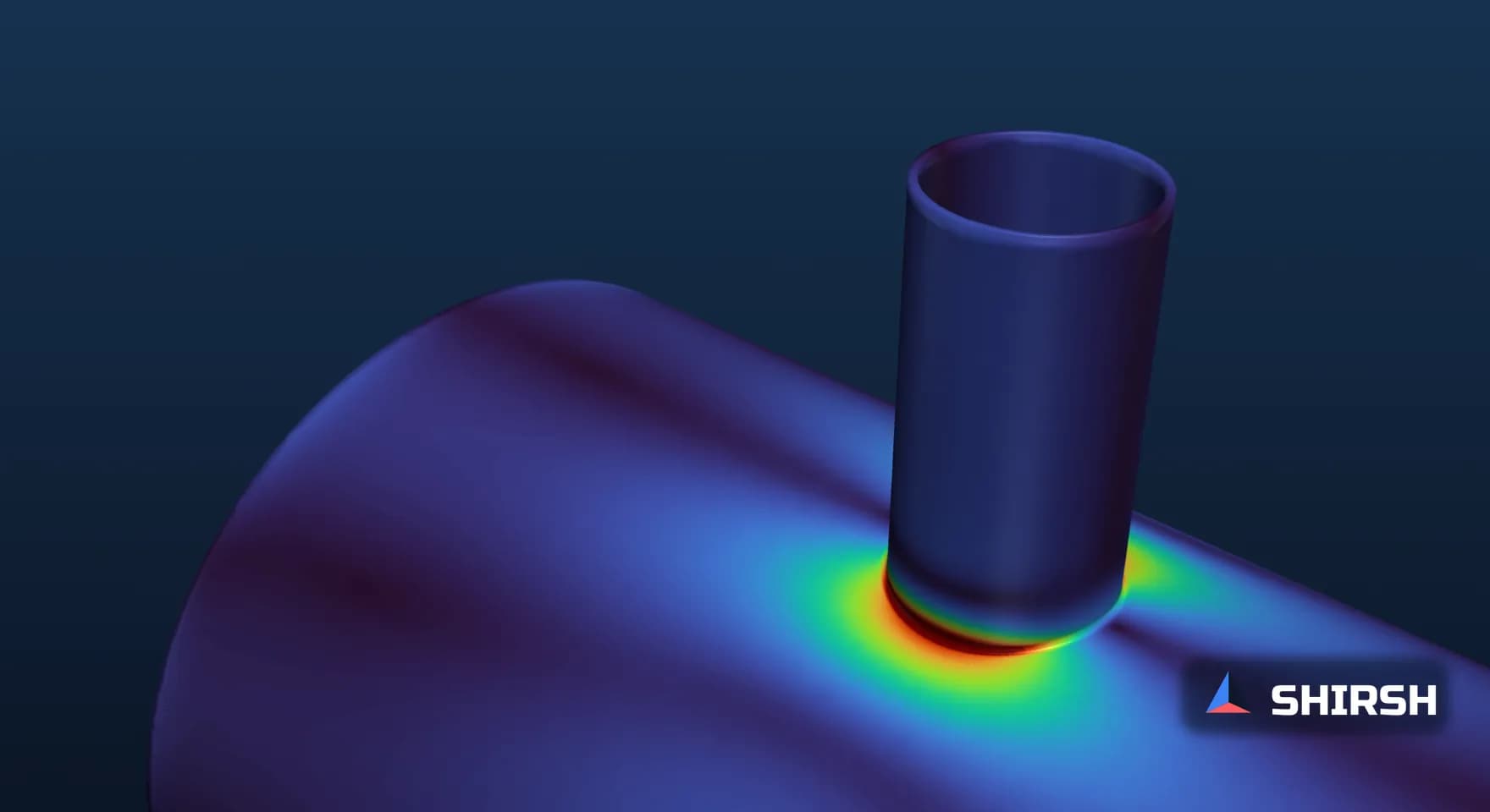
Von Mises stress on the 219 mm nozzle, mirrored from the quarter model. Under the longitudinal moment the hot band sits off the longitudinal plane; under the circumferential moment it sits on the transverse plane.
The peak includes the notch effect of the fillet, so we also swept the linearised stress on the nozzle-side SCL around the nozzle in 5° steps. For most cases the linearised maximum still falls on 0° or 90°, or within 5° of it. The exception is the 406 mm nozzle under ML, where the linearised value is 38.47 MPa at 30° against 36.78 MPa at 0°, about 4.6% higher. In this model the difference is small. It is still a reminder that the four reporting points are a convention of the hand method, and that an FE check should look all the way round before it picks a location.

Linearised membrane plus bending on the nozzle-side SCL around the nozzle, for each load and nozzle size. P and MC build towards 90°; ML is highest near 0° and, for the 406 mm nozzle, at 30°.
6. The nominal stress understates the junction more as the nozzle grows
Dividing the governing junction stress by the nominal neck stress gives a simple multiplier. Under MC it is 5.94 for the 114 mm nozzle, 12.88 for 219 mm, 19.84 for 406 mm and 19.71 for 610 mm. Under ML it is 4.15, 6.68, 7.33 and 7.60. Under P it is 11.68, 16.86, 16.97 and 17.61.
So a large nozzle on a thin shell can look lightly loaded on paper, a few MPa of nominal bending, and still put the highest multiplier on the junction. The absolute stresses on the 610 mm nozzle are small in this example only because the loads were kept the same for every size. Real piping loads on large nozzles are usually much larger, which is exactly where the multiplier matters.
7. Mesh check: the peak moves, the linearised value does not
On the 219 mm nozzle we ran three meshes, with 4, 2.5 and 1.6 mm elements in the weld fillet. The peak von Mises stress under MC rose from 288.58 to 319.28 and then 324.0 MPa. Under ML it went from 140.55 to 146.44 and 153.38 MPa, and its location shifted from 0° on the coarsest mesh to about 21° on the finer two. The linearised membrane plus bending on the governing nozzle-side line changed far less: 232.72, 232.67 and 229.90 MPa under MC, and 119.18, 119.24 and 119.19 MPa under ML.

Peak von Mises stress and linearised membrane plus bending on three meshes of the 219 mm nozzle. The linearised values used for the Part 5 checks stay within 1.3% across the meshes; the peaks are still moving.
Fillet element size, mm | Elements | Peak, MC, MPa | Linearised, MC, MPa | Peak, ML, MPa | Linearised, ML, MPa |
|---|---|---|---|---|---|
4 | 63,772 | 288.58 | 232.72 | 140.55 | 119.18 |
2.5 | 96,319 | 319.28 | 232.67 | 146.44 | 119.24 |
1.6 | 69,312 | 324.00 | 229.90 | 153.38 | 119.19 |
The finest mesh has fewer elements than the middle one because its refinement was kept within a few millimetres of the fillet. A peak that is still moving is fine for a linearised assessment, but it should not be used for fatigue without a proper peak stress or weld method.
8. What a nozzle load report should show
When we review a nozzle load report, by hand or by FEA, these are the things we look for:
The load table with its source, sign convention and load case, and which loads were treated as sustained and which as thermal expansion.
For a WRC calculation, the geometry parameters and a statement that they fall inside the bulletin's range, with pressure stress added separately.
Stresses in the nozzle wall as well as the shell, wherever the nozzle is thinner or the bulletin gives shell values only.
For an FE model, a neck check against beam theory, SCL positions on both sides of the junction, and a sweep around the nozzle rather than four points.
The classification behind each limit, with the Table 5.6 row named, and a mesh check on the linearised values used.
We move to FEA when the geometry is outside the bulletin, when a pad or another attachment sits within the local decay length, or when the nozzle wall is thinner than the shell.
Where Shirsh fits
At Shirsh Technosolutions we check nozzle loads for pressure vessels, columns, heat exchangers and tanks, with WRC methods where they apply and with ANSYS Mechanical models where they do not, and we write up the classification and the mesh check with the results. If you have a piping load table and a vessel that has to accept it, please get in touch.
References
ASME Boiler and Pressure Vessel Code, Section VIII Division 2, Part 5 (design by analysis, elastic stress analysis limits) and Annex 5-A (linearisation of stress results for stress classification), with Table 5.6 for stress classification.
Welding Research Council Bulletin 107, Local Stresses in Spherical and Cylindrical Shells due to External Loadings; WRC Bulletin 537 (equations for the WRC 107 curves); WRC Bulletin 297 (local stresses in cylindrical shells due to external loadings on nozzles).
Summaries of WRC 107 and WRC 297 applicability consulted for the differing limits: whatispiping.com, "Methods for WRC 107 (WRC 537) and WRC 297 checking", and epcland.com, "WRC 107, WRC 297 in Caesar II" (accessed 17 November 2026).
Worked example computed for this article on 17 November 2026: CalculiX quadratic tetrahedra, generic shell of 500 mm inside radius and 12 mm wall with radial nozzles of 114 to 610 mm outside diameter and 8 mm wall, P 10 kN, ML and MC 5 kN·m. Not any project.
Click to view full size
Related case studies

Want to Apply This to Your Product?
Our engineers can help you implement these techniques on your specific components and assemblies.
Get insights like this in your inbox
Engineering deep-dives, simulation tips, and industry analysis. No spam, unsubscribe any time.