
Design-by-Analysis of Two-Stage Reactor Cyclones to ASME VIII Div 2
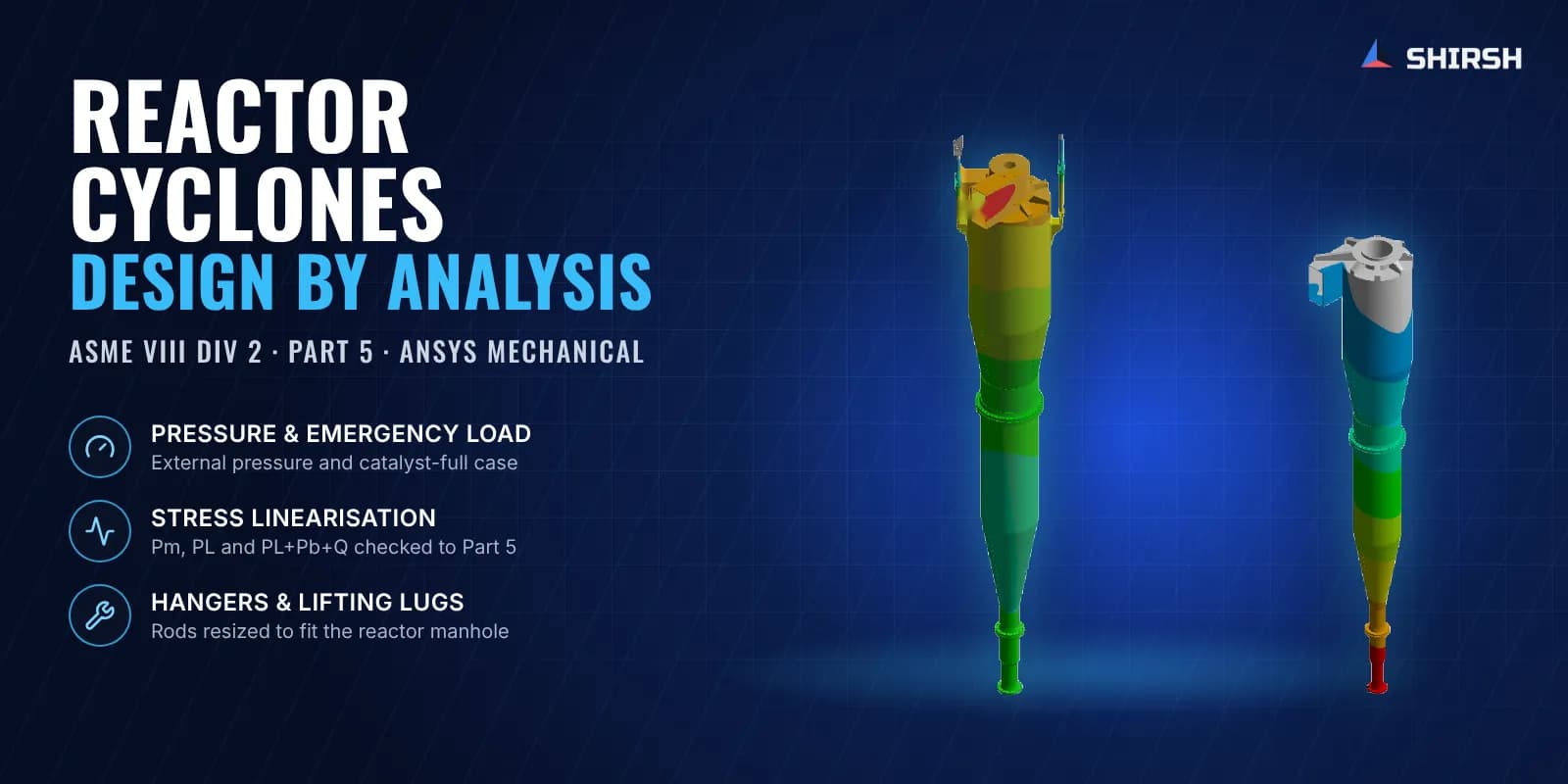
ASME VIII Div 2 design-by-analysis of hanging reactor cyclones, covering pressure, a catalyst-full emergency load, hanger rods and lifting lugs.
Project brief
A process equipment supplier was building first and second stage cyclones for a reactor at a chemical plant. The cyclones hang inside the reactor from hanger rods and lugs, so the whole set rides on a few small attachments. Before the EPC contractor would approve the drawings, the supplier needed a stress qualification to ASME Section VIII Division 2.
Shirsh Technosolutions did the design-by-analysis for both stages in ANSYS Mechanical. We stayed with the job while the support design changed, so the analysis guided those changes instead of only checking the final drawing.
What was at risk
Each cyclone is a long, thin-walled carbon steel vessel with a rib-stiffened roof, carried from the top on hanger rods. It runs at high temperature, which brings the allowable stress down, and the erosion allowance had to be taken off the walls and lugs before analysis.
The difficult case is the emergency load, with the cyclone filled with catalyst up to its inlet. The EPC also wanted the roof and stiffeners shown explicitly, a lifting lug check for fabrication and installation, and every remarked stress hotspot linearised and classified rather than read off a von Mises plot.
In the first round of analysis the first stage hanger supports did not pass. Any fix had to respect a hard limit: the cyclone still had to go in through the reactor manhole.
Solution offered
We built 3D models of both stages from the fabrication drawings and meshed them with second-order elements, with enough elements through each wall to capture bending, and checked mesh convergence on stress. A steady-state thermal run set the metal temperature, which then drove the material properties and allowables taken from ASME Section II Part D.
Three load combinations were run for each stage:
Load case 1: empty weight with external pressure acting on the shell.
Load case 2: empty weight plus the emergency weight, with catalyst filled to the inlet.
Load case 3: the lifting lugs, holding the lower cyclone during fabrication and installation.
The evaluation followed ASME VIII Div 2 Part 5 elastic stress analysis. Stresses were linearised through the thickness at the critical sections, classified as Pm, PL and PL+Pb+Q, and checked against their limits. Wherever the reviewer had marked a peak, the linearised value was reported against its proper limit.
For the failing hangers we compared two options: sharing the load with a nozzle on the cyclone top, or increasing the hanger rod size up to the largest that fitted the existing lugs and still passed the manhole. The larger rods were taken forward, and the lifting lug geometry was revised and re-checked.
Common questions
Why linearise stresses instead of using peak von Mises? ASME VIII Div 2 Part 5 limits membrane and bending stress categories, not local peaks. A von Mises hotspot at a hanger weld can look alarming on a contour plot while its linearised PL+Pb+Q sits well inside the limit.
What makes hanging cyclones hard to qualify? The whole weight, including a catalyst-full upset case, goes through a few hanger rods and lugs. Those attachments are also constrained by erosion allowance and by the size of the reactor manhole.
Challenges we overcame
Thin shell with the erosion allowance removed before analysis, at high design temperature
Catalyst-full emergency load carried entirely through the hanger rods and lugs
First-stage hanger supports failing in the first round of analysis
Hanger rod size capped by the reactor manhole and by the existing support lugs
Reviewer demand to linearise and classify every marked hotspot instead of reporting peak von Mises
Support configuration changing during the job, including removal of a nozzle
How we executed
- 1
Built 3D models of both cyclone stages from the fabrication drawings, with the erosion allowance deducted
- 2
Meshed with second-order elements, several through each wall, and checked mesh convergence on stress
- 3
Ran a steady-state thermal analysis to set metal temperature and temperature-dependent properties
- 4
Applied empty weight with external pressure, then the catalyst-full emergency load
- 5
Linearised stresses at critical sections and checked Pm, PL and PL+Pb+Q against their ASME limits
- 6
Compared hanger fixes, nozzle load sharing against larger rods, within the manhole limit
- 7
Added the roof and rib stress check and the lifting lug case for fabrication and installation
- 8
Updated the analysis as the support design changed, through to the final configuration
Project outcome
Both cyclone stages were shown acceptable to ASME VIII Div 2 Part 5.
In the emergency case, membrane and combined stresses stayed within the code limits for both stages.
The hanger problem was solved with larger rods that still let the cyclone pass the reactor manhole, without enlarging the lugs.
The roof, ribs and lifting lugs were documented as the EPC reviewer asked, and the linearisation comments were answered.
The supplier had a code-based analysis to submit for drawing approval.
Project gallery
Where this lives
Software used
Related solutions
At a glance
We apply the same rigour to every engagement
Let us show you what's possible for your product.