ASME VIII Div 2 Stress Linearisation: SCL Placement and Traps
On a flat head model with a sharp inside corner, the corner peak rose from 483.5 to 1222.1 MPa as the mesh was refined, while the linearised stress 5 mm away held at about 310 MPa. We use that worked example to show where stress classification lines belong, what linearisation keeps, and how one classification call turns a pass into a fail.
Read the full article below for the methodology, the data, and the engineering decisions behind it.
Design by analysis to ASME Section VIII Division 2 looks simple on paper. Run a linear elastic model, draw a line through the wall, split the stress on that line into membrane, bending and peak, and compare each part with its limit. In practice almost every argument we see between an analyst and a reviewer comes back to two choices made before any limit is checked: where the line was drawn, and what the bending on it was called.
This article works through both with a small model we solved for it, a cylindrical shell closed by a flat head under internal pressure. The numbers are generic and belong to this model only. The traps are the ones we meet in real reports.
1. What Part 5 asks for
Part 5 offers three routes for protection against plastic collapse: elastic stress analysis (5.2.2), limit-load analysis (5.2.3) and elastic-plastic stress analysis (5.2.4). Only the elastic route needs stresses to be classified. The assessment in 5.2.2.4 compares equivalent stresses built from the categories with their allowables: general primary membrane Pm against S, local primary membrane PL against 1.5S, primary membrane plus primary bending PL + Pb against 1.5S. The secondary range PL + Pb + Q is checked separately under the ratcheting rules of 5.5.6 against SPS, the larger of 3S and 2Sy where that is permitted. Peak stress F only enters fatigue.
The categories come from Table 5.6, which lists typical locations in a vessel and says which stress at each location belongs where. For a cylindrical shell remote from discontinuities, membrane is Pm and the through-wall gradient is Q. At the junction with a head or flange, the membrane is PL and the bending is Q. For a flat head, the bending in the centre region is primary, Pb, and the bending at the junction to the shell is Q, with a note that changes it to Pb when the edge moment is needed to keep the centre bending within its limit. We come back to that note in section 6.
Annex 5-A gives the procedure for turning a finite element stress field into those categories. Stresses are taken along a stress classification line (SCL) through the wall. The membrane part is the average of each component along the line. The bending part is the linear moment term, and it is computed only for the two normal stresses that act in the plane of the wall, hoop and meridional in a shell. The through-thickness normal stress and the shear stresses carry no bending term. What is left after membrane and bending is the peak.
2. The worked example
The model is a cylindrical shell of 500 mm inside radius and 20 mm wall, closed by a 50 mm flat plate welded to its end, under an internal pressure of 2 MPa. Half the vessel length, 1000 mm of shell, is modelled with a symmetry plane at mid-length, so the axial stress in the shell comes from the pressure on the head. The model is axisymmetric and linear elastic, with E = 200 GPa and Poisson's ratio 0.3, solved in scikit-fem with nine-node quadratic quadrilaterals. The inside corner where the shell meets the head is left perfectly sharp, as it is in most models built from a drawing.
For the limit comparisons we take S = 138 MPa as an example value, so 1.5S is 207 MPa and 3S is 414 MPa. A real assessment takes S from Section II Part D for the actual material and temperature.
We drew six SCLs. S1 crosses the shell at 600 mm from the head, well clear of the junction. S2 crosses the shell wall right at the junction, starting at the sharp corner. S3 crosses the shell 5 mm above it. S4 runs through the head thickness on the axis. S5 runs through the head thickness 5 mm in from the shell's inside wall. S6 starts at the corner but runs to a point 20 mm up the outside of the shell, so it is skewed instead of normal to the wall.

Figure 1. The model and the stress classification lines used in this article.
3. First check: the remote shell
Far from the head the shell should behave like a textbook pressure cylinder, and it does. The thick-wall (Lamé) solution gives an average hoop stress of 50.0 MPa, an axial stress of 24.51 MPa and an average radial stress of -0.98 MPa, which make a von Mises membrane stress of 44.15 MPa. Linearised along S1, the model gives Pm = 44.07 MPa. That is 32% of S, and it tells us the model and the post-processing agree with hand theory before we look at anything harder.
4. The trap at the corner
Now look at the junction. The highest von Mises stress in the model sits exactly at the sharp inside corner, and it does not settle as the mesh is refined. We solved the same model with element sizes in the wall of 5, 2.5, 1.25 and 0.625 mm.
Element size (mm) | Elements | Corner peak (MPa) | S2 through the corner, membrane + bending (MPa) | S3, 5 mm away, membrane + bending (MPa) | S1 remote, membrane (MPa) |
|---|---|---|---|---|---|
5 | 1,334 | 483.5 | 342.87 | 309.94 | 44.07 |
2.5 | 3,964 | 657.6 | 349.84 | 310.48 | 44.07 |
1.25 | 12,000 | 896.6 | 354.59 | 309.63 | 44.07 |
0.625 | 37,520 | 1222.1 | 358.14 | 309.46 | 44.07 |
The corner peak grows by a factor of 2.53 over the four meshes and would keep growing. It is a singularity of the sharp-cornered elastic model, and no number in that column belongs in a report. The linearised value on S3 changes by less than 0.4% across the same meshes. That is the point of linearisation: the membrane and bending resultants are integrals across the wall, and they converge even where the local peak does not.
S2 sits in between. Because it starts on the singular point, its membrane plus bending creeps upward with every refinement, from 342.87 to 358.14 MPa, and on the 1.25 mm mesh it reads 14.5% above S3. Its membrane also picks up a through-thickness stress of 88.71 MPa, which is the head pressing on the shell end, not membrane action in the shell. An SCL laid exactly along the junction plane reads the junction, not the shell.

Figure 2. Mesh refinement. The corner peak runs away while the linearised values settle.

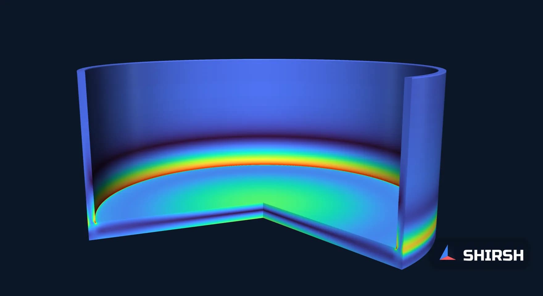
Figure 3. Von Mises stress at the junction on the 1.25 mm mesh, capped at 400 MPa so the rest of the field stays readable.
5. Where the line goes, and which way it points
Annex 5-A expects SCLs at the gross structural discontinuities, running through the thickness and normal to the mid-surface. Two details decide whether the result means anything.
The first is orientation. S6 starts at the same corner as S2 but runs at an angle to the outside surface 20 mm up the shell. Its membrane rises to 106.72 MPa, 15% above S2, while its membrane plus bending drops to 236.88 MPa, a third lower. A skewed line mixes the meridional and through-thickness components and stretches the lever arm, so the bending it reports is simply smaller. On this junction that is the unconservative direction.
The second is position. Moving the shell SCL away from the head shows how quickly the junction bending dies out. On the 1.25 mm mesh the membrane plus bending falls from 309.63 MPa at 5 mm to 209.46 MPa at 30 mm and 38.71 MPa at 100 mm, which is about the length √(Rt) of this shell, 101 mm. An SCL placed a few wall thicknesses from the junction will pass a check that the junction itself fails. We place the line at the junction, check one or two lines just clear of any singular point, and report the highest stable value.

Figure 4. Linearised stress on the shell against the SCL position, with the example limits.

Figure 5. Along S3 the meridional and hoop stresses are close to linear through the wall, which is the condition under which linearisation describes the section well.
6. The classification call
With the line in the right place, the remaining decision is what to call the bending. On S3 the numbers are PL = 69.15 MPa and membrane plus bending = 309.63 MPa, governed by the inside surface of the shell. On the head lines S4 and S5 the outside surface governs.
SCL | Quantity | Value (MPa) | Read as | Limit (MPa) | Outcome |
|---|---|---|---|---|---|
S1 shell, remote | Membrane | 44.07 | Pm | S = 138 | Pass |
S3 shell junction | Membrane | 69.15 | PL | 1.5S = 207 | Pass |
S3 shell junction | Membrane + bending | 309.63 | PL + Pb + Q, bending as Q | 3S = 414 | Pass |
S3 shell junction | Membrane + bending | 309.63 | PL + Pb, bending as Pb | 1.5S = 207 | Fail |
S4 head centre | Membrane + bending | 184.59 | Pm + Pb | 1.5S = 207 | Pass |
S5 head edge | Membrane + bending | 96.71 | PL + Pb (Table 5.6 note) | 1.5S = 207 | Pass |
Read as secondary, the junction bending uses 75% of 3S. Read as primary, it is 1.5 times the 1.5S limit.
Table 5.6 settles the flat head itself through its note, and the test is easy to run. The head centre carries 184.59 MPa of membrane plus bending on the axis, 89% of 1.5S. If the edge gave no moment at all, a simply supported plate of 500 mm radius and 50 mm thickness would carry a centre bending stress of 3(3 + ν)pa²/8t² = 247.5 MPa (Roark, simply supported circular plate under uniform pressure), which is above 207 MPa. So the edge moment is needed to keep the centre within its limit, and the head-edge bending on S5 is primary. At 96.71 MPa it passes with room.
The harder question is the shell. The moment the head edge needs is delivered by the end of the shell, and Table 5.6 lists the shell's junction bending as Q. Whether that same moment should be treated as primary on the shell side is a judgement the code leaves to the analyst, and we have seen it argued both ways in design reviews. In this example it decides the outcome. Our practice is to report both readings, state which one the assessment adopts and why, and when the primary reading fails, move to a limit-load or elastic-plastic check under 5.2.3 or 5.2.4, where no classification is needed at all.
7. A reviewer's checklist
What you see in the report | Why it matters | What to ask for |
|---|---|---|
Peak stress at a sharp corner quoted against an allowable | The value depends on the mesh and does not converge | Linearised values on SCLs, with the peak used only for fatigue |
SCL starting exactly on a singular point | Membrane and bending creep with refinement | A line just clear of the point, and a mesh check on that line |
SCL not normal to the wall | Bending can be understated by a third, as in this example | A sketch or plot showing each SCL on the geometry |
SCLs only at convenient locations away from the junction | Junction bending dies out within about √(Rt) | Lines at every gross discontinuity, plus a short position sweep |
Junction bending called Q without comment | The flat-head note in Table 5.6 can make it Pb | The test that was applied, and the margin under both readings |
Only von Mises totals tabulated | The categories cannot be checked | Membrane and bending components per SCL, with the surface that governs |
Where Shirsh fits
We carry out design by analysis to ASME Section VIII Division 2 in ANSYS Mechanical and, where it helps, in open-source codes such as Code_Aster and CalculiX, and we review Part 5 reports prepared by others. Most of that review work comes down to where the SCLs were drawn and how the bending was classified, and to making sure both are shown clearly enough for an inspector to follow. If you have a vessel, nozzle or flange assessment that needs to stand up to that kind of reading, please get in touch.
References
ASME Boiler and Pressure Vessel Code, Section VIII, Division 2, Part 5 (5.2.2 elastic stress analysis and 5.2.2.4 assessment procedure, 5.2.3 limit-load analysis, 5.2.4 elastic-plastic stress analysis, 5.5.6 ratcheting, Table 5.6 stress classification examples) and Annex 5-A, linearisation of stress results for stress classification.
J. L. Hechmer and G. L. Hollinger, 3D Stress Criteria: Guidelines for Application, WRC Bulletin 429, Welding Research Council, 1998.
D. Mackenzie, Stress linearization concepts and restrictions in elastic design by analysis, ASME PVP2017.
W. C. Young and R. G. Budynas, Roark's Formulas for Stress and Strain, simply supported circular plate under uniform pressure.
Worked example (axisymmetric scikit-fem model, four meshes, Annex 5-A stress integration on six SCLs) computed for this article, 13 November 2026. Generic geometry; not any project.
Click to view full size
Related case studies
Want to Apply This to Your Product?
Our engineers can help you implement these techniques on your specific components and assemblies.
Get insights like this in your inbox
Engineering deep-dives, simulation tips, and industry analysis. No spam, unsubscribe any time.