Swing Check Valve CFD: Pressure Drop and Flow at Every Disc Opening
Swing check valve CFD in ANSYS Fluent. Pressure drop across the flow range and flow at each disc opening, with a documented method for the valve maker.
Project brief
A valve manufacturer wanted hard flow data for a large-bore swing check valve from its range. Its customers ask how much pressure the valve costs at different flow rates and how much it passes when the disc is only partly open, and many of them know CFD well enough to question the method behind any number.
Shirsh Technosolutions carried out the swing check valve CFD in ANSYS Fluent on the maker's own 3D assembly. We built a pressure drop curve across the working flow range and a flow curve across disc positions from a small opening up to fully open, and wrote up the method, mesh, turbulence model, boundary conditions and convergence evidence in a detailed report so the maker could put the results in front of its customers with confidence.
What was at risk
A swing check valve has one moving part, a hinged disc that the flow lifts and gravity and back-pressure close. In service the disc rarely sits fully open. At lower flows it hangs part way, and the gap between disc and seat decides both the pressure loss and how much the valve can pass.
Catalogue figures for this kind of valve are often taken from simple correlations or from a single fully open test. The maker needed something better for its customers:
the pressure drop across the valve for a range of line velocities, read as a curve rather than one point
the flow the valve passes at each disc opening for a fixed pressure difference
an analysis method clear enough that a customer's own CFD engineer could follow it, check the assumptions and trust the accuracy
The first summary of results also raised a practical point. The client asked for a full write-up of methodology and assumptions, the software named, and images of the complete valve assembly, so the final deliverable had to read as a complete engineering report that a reviewer could follow step by step.
Solution offered
Geometry and flow volume. The maker supplied the valve assembly as a 3D model. We cleaned it up, extracted the internal flow volume through body, bonnet cavity, disc and hinge arm, and extended the inlet and outlet so the flow could develop before and after the valve. A separate flow volume was set up for each disc position, from a small opening in steps up to fully open.
Mesh. The volumes were meshed in Ansys Fluent meshing with a poly-hexcore mesh: hexahedral cells in the bore and polyhedral cells around the disc, hinge arm and seat, where the gaps are narrow and the gradients steep. Cell quality was checked on every model before solving.
CFD set-up in ANSYS Fluent.
Three-dimensional, steady-state, incompressible turbulent flow of water.
k-ω SST turbulence model, which handles the separation behind the disc and the recirculation in the bonnet cavity better than the standard k-ε family.
Pressure-based coupled solver, second-order pressure and momentum discretisation.
Two sets of boundary conditions. For the pressure drop curve, a velocity inlet stepped across the working range with a pressure outlet. For the opening sweep, a pressure inlet and pressure outlet holding a constant pressure difference, so the flow at each disc position could be compared on equal terms.
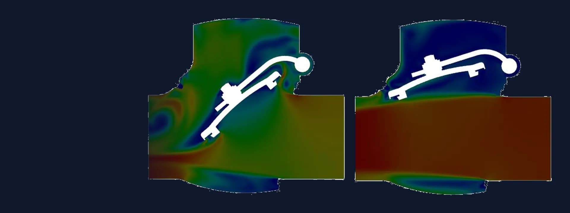
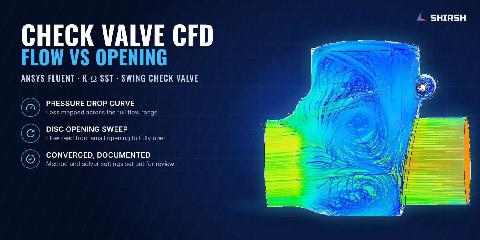
Results read for the maker. For every disc position we reported velocity contours on the central plane, velocity on the inlet and outlet faces and velocity profiles across both, along with 3D streamlines and vectors that show the jet under the disc and the swirl in the bonnet. The pressure drop was tabulated and plotted against flow rate, and flow rate and average inlet and outlet velocity were tabulated against disc opening. Residual histories were included to show each run had converged.
Common questions
What does CFD tell you about a swing check valve? It gives the pressure loss across the valve at any flow rate and shows how much flow passes when the disc is only partly open. The flow field also shows where the jet under the disc and the recirculation in the bonnet cavity sit, which helps when comparing body and disc shapes.
Why model several disc openings instead of only fully open? In service the disc of a swing check valve often hangs part way, especially at lower flows. Modelling a series of openings shows how flow capacity builds up with disc lift, which a single fully open result cannot.
Challenges we overcame
A hinged disc whose position changes the flow passage completely
Narrow gaps around the disc, hinge arm and seat that needed a fine, good-quality mesh
Separation behind the disc and recirculation in the bonnet cavity
Two different questions, loss versus flow and flow versus opening, needing separate boundary conditions
A deliverable that had to stand up to customers who know CFD themselves
How we executed
- 1
Received the valve assembly model and the starting line velocity from the manufacturer
- 2
Cleaned the geometry and extracted the internal flow volume with extended inlet and outlet pipes
- 3
Built a separate flow volume for each disc position from a small opening up to fully open
- 4
Meshed each volume with a poly-hexcore mesh in Ansys Fluent meshing and checked cell quality
- 5
Solved steady, incompressible turbulent flow of water in ANSYS Fluent with the k-ω SST model
- 6
Ran a series of inlet velocities across the working range and read the pressure drop for each
- 7
Held a constant pressure difference across the valve and read the flow at each disc opening
- 8
Shared a snapshot of results, took the client's comments and issued a detailed report with method, assumptions, software, assembly images and convergence evidence
Project outcome
A pressure drop versus flow rate curve for the valve across its working range, ready for the maker's technical literature.
Flow rate and average inlet and outlet velocity at each disc position, showing how capacity builds up as the disc lifts.
Flow field images that show the jet under the disc and the recirculation in the bonnet cavity at every opening.
A documented method with mesh quality and converged residuals that the maker could share with its customers.
Project gallery
Where this lives
Software used
Related solutions
Industries
At a glance
We apply the same rigour to every engagement
Let us show you what's possible for your product.