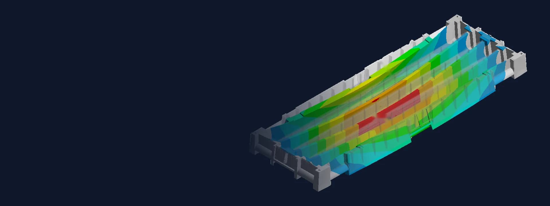
Core Tray Stack FEA: Strength, Transport Vibration and Fatigue of a Polymer Tray
Polymer core tray FEA in ANSYS: elastic-plastic stacking and handling loads, random transport vibration and fatigue life before mould release.
Project brief
A polymer products manufacturer had designed an injection-moulded tray for storing drill core samples. In use these trays are filled with heavy rock core, stacked high in core sheds, picked up by hand from either end and carried on trucks over rough roads. Before committing to the mould, the client wanted to know how the design would hold up in all of that, and it wanted the check done in simulation rather than by trial moulding.
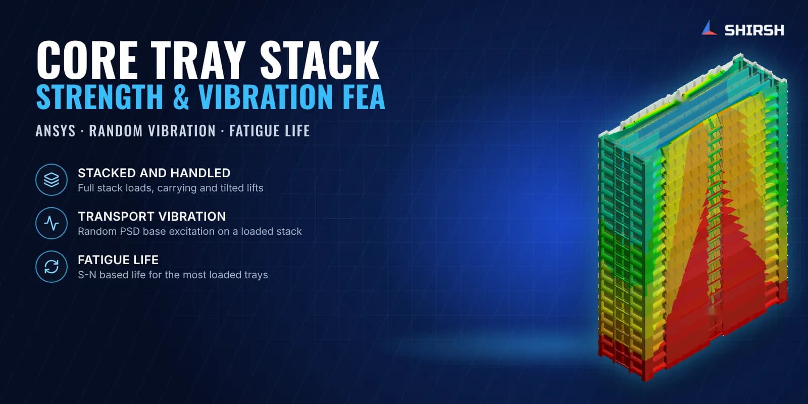
Shirsh Technosolutions ran a core tray FEA in ANSYS Mechanical covering static stacking and handling loads, transport vibration and fatigue. The study used elastic-plastic material data for the client's polypropylene copolymer grade, modelled single trays as well as tall stacks, and gave the client clear pictures of where the tray deflects and where stress concentrates, ready for its discussion with the mould maker.
What was at risk
A core tray looks simple, but it carries a lot. The bottom tray in a stack takes the weight of every loaded tray above it, a tray lifted by its end handles bends along its full length with all the core inside, and on a truck the whole stack is shaken for hours. Polymer also creeps and yields well before steel would, so a linear check could miss what really happens at the ribs and handle corners.
The client had listed the conditions it wanted checked, from crushing and bending of a loaded tray to handle strength, stack stability and transport jerks. It needed:
the bottom and second-bottom trays checked under the full weight of a loaded stack
loaded trays checked when carried from the long side, the short side and when lifted at an angle
the behaviour of complete stacks under their own weight and the core load
a transport vibration check of a loaded tray at the bottom of a stack
a fatigue life estimate for the most heavily loaded trays
Solution offered
Model and material. The tray CAD shared by the client was meshed in ANSYS Mechanical. The client's raw-material supplier gave the modulus and Poisson's ratio range for the grade, and the study used a multilinear isotropic hardening curve and an S-N curve for the polypropylene copolymer, so the static cases were run as elastic-plastic analyses and the same material data fed the fatigue step.
Stacking and handling cases. Core load was applied in each channel of the tray and the weight of the trays above was applied as a stack load on the bottom and second-bottom trays. Handling was modelled with support only where hands or lifting points hold the tray: carried from the long side, from the short side, and tilted from either edge. Complete stacks of different heights were also modelled tray by tray to see how the whole column deflects in each direction.
Transport vibration. A modal analysis of the loaded bottom tray was followed by a random vibration analysis with a road-transport PSD as base excitation, in two horizontal directions and for two stack heights. Deformation and stress were read at the one-sigma level.
Fatigue. Fatigue life was calculated for the bottom and second-bottom trays under stack load, using the S-N data of the grade.
Results read with the client. The report shows deformation and stress for every case, with zoomed views at the local hot spots. After a review meeting, the ANSYS result files for the critical cases were also shared so the client could study them with its mould maker.
Common questions
Why use elastic-plastic FEA for a plastic tray? Polymers start to yield at fairly low stress, so a linear model can overstate stress at ribs and corners and misjudge how the tray really behaves. A multilinear hardening curve from the material data lets local yielding redistribute load the way the moulded part would.
How is transport vibration checked in simulation? A modal analysis finds the natural frequencies of the loaded tray, then a random vibration analysis applies a road-transport acceleration spectrum (PSD) at the base. The result gives statistical deformation and stress levels that can be compared with the material's allowable.
Challenges we overcame
A polymer that yields early, which needed elastic-plastic material data rather than a linear check
The bottom tray of a tall stack carrying the weight of every loaded tray above it
Hand-carry and tilted-lift cases where the tray is held only at a few points
Whole stacks modelled tray by tray to see how the column deflects
Transport vibration defined as a random PSD rather than a single static jerk
How we executed
- 1
Received the tray CAD, the list of service conditions and the material grade data from the client
- 2
Set up a multilinear hardening curve and an S-N curve for the polypropylene copolymer
- 3
Applied core load per channel and the stack load on the bottom and second-bottom trays
- 4
Ran hand-carry cases from the long and short sides and tilted-lift cases from each edge
- 5
Modelled complete stacks tray by tray and read deformation in all three directions
- 6
Ran modal and random vibration analyses with a road-transport PSD in two directions
- 7
Calculated fatigue life for the bottom and second-bottom trays
- 8
Reviewed the results with the client and shared result files for the critical cases for the mould discussion
Project outcome
Stresses in all static stacking and handling cases were within the allowable in the elastic-plastic analysis.
Stresses under random transport vibration were within the allowable for all the cases run.
Fatigue life was estimated for the most heavily loaded trays, with the second-bottom tray found to be the more critical of the two.
Local stress areas at ribs and supports were pointed out for the client's discussion with its mould maker before the design was frozen.
Project gallery
Where this lives
Software used
Related solutions
Industries
At a glance
We apply the same rigour to every engagement
Let us show you what's possible for your product.